background image

125

B_03699

B_04764

B_05892

B_05893

B_05894

B_05895

B_05986

B_05987

OPERATING MANUAL

EDITION 02/2016

ORDER NUMBER DOC 2366600

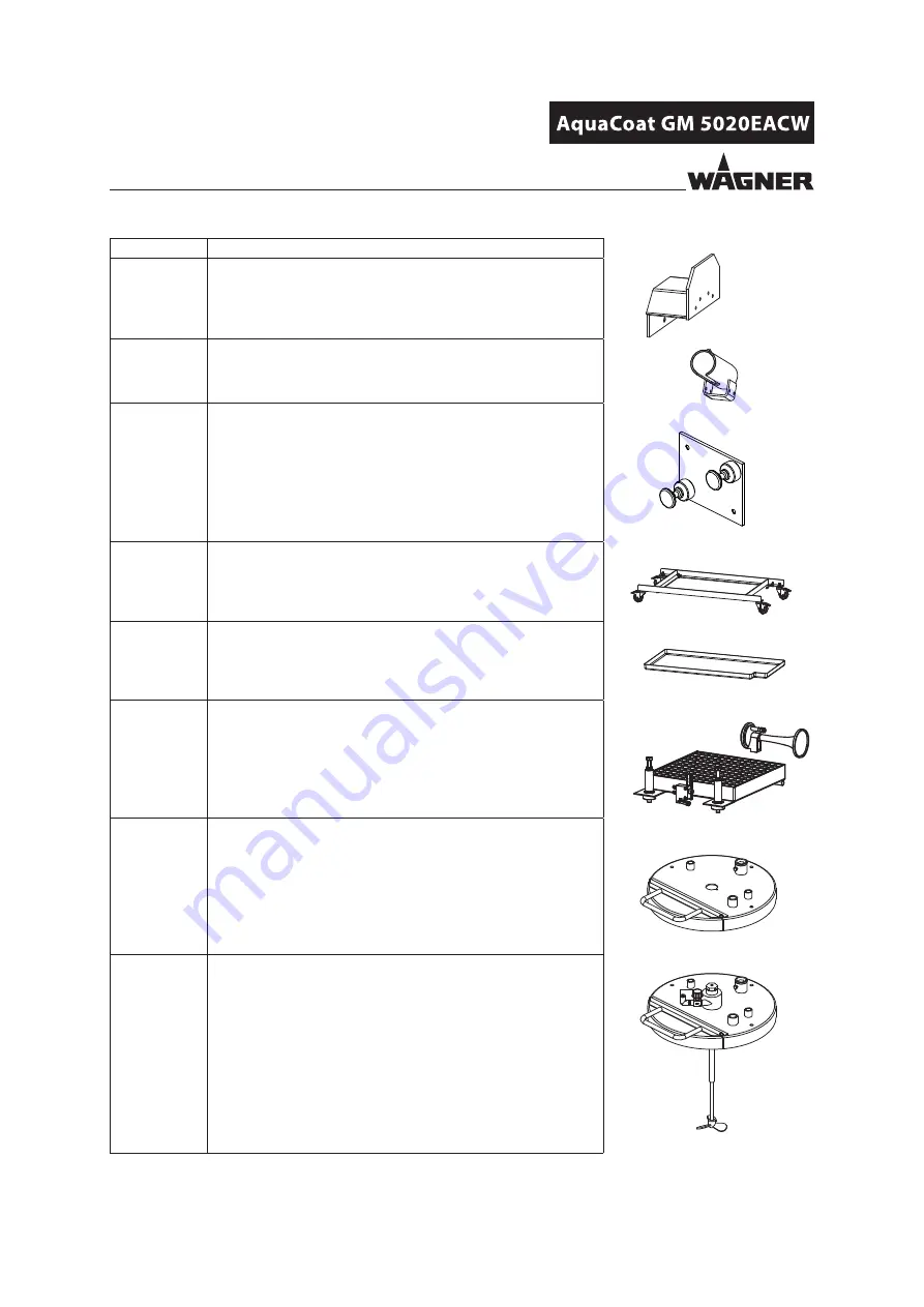
Order No.

Designation

353050

Hose holder

2359097

Gun holder.
For assembly on hose holder 353050.

2326485

Wall mount, GM 5000E (left/right)

2359029

Underframe, 5020 with rolls

2364394

Underframe, 5010 with rolls

2364791

Tub insert, 5020

2364790

Tub insert, 5010

353053

Level monitor, incl. alarm horn

353054

Drum cover, D350 without agitator

353055

Drum cover, D350 with agitator

Summary of Contents for AquaCoat 5010

Page 1: ...B_05900 AirCoat Spraying System for Non flammable Liquids Version 02 2016 Translation of the Original Operating Manual Manual GM 5020EACW High pressure...

Page 2: ......

Page 3: ...RAL SAFETY INSTRUCTIONS 15 4 1 Safety Instructions for the Operator 15 4 1 1 Electrical Equipment 15 4 1 2 Personnel Qualifications 15 4 1 3 Safe Work Environment 15 4 2 Safety Instructions for Staff...

Page 4: ...Assembly Commissioning Staff 44 6 2 Storage Conditions 44 6 3 Installation Conditions 44 6 4 Transportation 45 6 5 Assembly and Installation 45 6 5 1 Assembling the AquaCoat System 46 6 5 2 Ventilati...

Page 5: ...18 Service Display Setup 83 7 3 19 Carry Out Service Display 84 7 4 Device Configuration 85 7 4 1 Overview of Parameters 85 7 4 2 Access to the Device Configuration Mode 86 7 4 3 Setting Example Para...

Page 6: ...Spare Parts Be Ordered 126 14 2 AquaCoat Basic device 127 14 2 1 VM 5020W Control Unit 132 14 3 Pump Sets 138 14 3 1 Puma 28 40 Set for AquaCoat 138 14 3 2 Cobra 40 10 Set for AquaCoat 140 14 3 3 EvoM...

Page 7: ...s injury Warning possible imminent danger Non observance may result in death or serious injury Caution a possibly hazardous situation Non observance may result in minor injury Notice a possibly hazard...

Page 8: ...2333538 French 2333539 Italian 2333540 Spanish 2333541 AquaCoat compressed air connection for Puma Refer to Chapter 5 6 2 1 Double diaphragm pump Cobra 40 10 operating manual Language Order No Languag...

Page 9: ...ining knowledge and experience in relevant provisions Skilled person A person who based on his her technical training experience and recent vocational experience has sufficient technical knowledge and...

Page 10: ...re parts catalog 2 2 TYPE OF USE 2 3 USE IN AN EXPLOSION HAZARD AREA The device is not suitable for use in potentially explosive areas See Chapter 3 1 CE Identification WAGNER accepts no liability for...

Page 11: ...have like water in liquid form liquid phase and in sprayed form Thinners must also be non flammable If the cleaning and flushing agents also align with this category the system may be used Example of...

Page 12: ...cts e g powder using defective components spare parts or accessories other than those described in the Accessories chapter of this operating manual continuing work with a defective or kinked product h...

Page 13: ...Serie Nr Serial No Spannung Voltage Artikel Nr Article No Eingangsleistung Line Power Schutzart IP Code Norm Standard EN 50059 IP 40 Spannung Voltage Strom Current max 20Vpp max 1 0A Baujahr Year of...

Page 14: ...f the system is grounded and the door lock opened AquaCoat cabinet GM 5020EACW spray gun 1 Gun type 2 Article number 3 Maximum high voltage Energy 4 Maximum product pressure 5 Maximum air pressure 6 I...

Page 15: ...erve electrical safety regulations Ground all devices to a common grounding point Only operate the device with a properly installed socket with a protective ground wire connection Keep liquids away fr...

Page 16: ...o have repairs carried out immediately Grounding Make sure that the ground and potential equalization of all system parts are performed reliably and continuously and can withstand the expected stress...

Page 17: ...e never used to pull or move the equipment The electrical resistance of the product hose outer sheath measured over the entire length of the outer sheath must be less than 1 megohm Suction hoses may n...

Page 18: ...sed tank when using solvents for flushing External cleaning When cleaning the exterior of the device or its parts also observe the following Disconnect the pneumatic supply line Use only moistened clo...

Page 19: ...gles protective clothing and gloves as well as respiratory protection and skin protection cream if necessary Use a mask or breathing apparatus if necessary For sufficient health and environmental safe...

Page 20: ...abinet 2 Cabinet door 3 VM 5020W control unit 4 GM 5020EACW spray gun 5 Hose set EACW 6 Product hose Puma from high pressure filter to spray gun Cobra from high pressure filter to potential equalizati...

Page 21: ...15 Grounding bolt on the cabinet door 16 Grounding band in the cabinet door 17 Electrical door switch 18 Pneumatic door switch 20 Air hose pump air supply 21 Air hose for the air motor reversing valv...

Page 22: ...inlet with ball valve 9 Inlet for mains cable 10 Grounding terminal input grounding cable 11 Product pressure generator pump 12 High pressure filter 13 Suction system Pos Designation 14 Metallic produ...

Page 23: ...e product hose 36 Grounding point The AquaCoat spray system is designed for processing non combustible liquids water based lacquers in accordance with the AirCoat method The spray product is regulated...

Page 24: ...a EvoMotion or the stripped part of the product hose for Cobra Electrical door switch 17 The grounding switch is closed with an open cabinet door potential equalization lines are grounded Pneumatic do...

Page 25: ...the other hand there is the outer shell of the product hose from a conductive grounded plastic sheath Even of an electrical breakdown of the product hose there is no danger to the user since the curr...

Page 26: ...indow B_05974 With window G B_05975 Example Example AquaCoat 5020 AquaCoat 5020G Pomp set Pomp set Puma 28 40 Cobra 40 10 EvoMotion 20 30 Designation Order No Order No Order No Pomp set 2363746 236374...

Page 27: ...basic device 2363734 4 AquaCoat 5010G manual basic device 2363736 Pomp set 5 Puma 28 40 set for AquaCoat 2363746 6 Cobra 40 10 set for AquaCoat 2363747 7 EvoMotion 20 30 set for AquaCoat 2363946 Spra...

Page 28: ...4 8 bar 58 116 psi Compressed air quality free from oil and water Quality standard 6 5 2 according to ISO 8573 1 2010 6 Particle density 5 mg m3 5 Humidity pressure dew point 7 C 2 Oil content 0 1 mg...

Page 29: ...50 Hz 60 Hz Input power Max 40 W Output voltage Max 20 Output current Max 1 0 High voltage Max 70 Spray current Max 100 Operating temperature range 5 40 C 41 104 F Protection class IP 40 Weight withou...

Page 30: ...duct pressure 25 MPa 250 bar 3 626 psi Fluid inlet NPSM 1 4 18 Air connection G 1 4 A Weight without hose set 700 g 1 54 lb incl union nut nozzle and air cap Operating temperature range 5 C up to 40 C...

Page 31: ...ITION 02 2016 ORDER NUMBER DOC 2366600 5 5 4 ELECTRIC BLOCK DIAGRAM AQUACOAT Connection Function J2 Gun connection J3 External interface see Chapter 7 5 VM 5020W control unit Cabinet Grounding switch...

Page 32: ...IDE 1 Selector mains supply 0 Control unit switched off 1 Control unit switched on 2 Universal control dial Dynamic digital control dial with 32 positions per revolution Adjustment speed is proportion...

Page 33: ...y shaping and atomizing air to the spray gun Adjusting range 0 1 0 MPa 0 10 bar 0 145 psi 12 Pressure gauge Atomizing air Air pressure display for the spray gun Display range 0 1 0 MPa 0 10 bar 0 145...

Page 34: ...ngle LED display Nominal voltage Bar display Working voltage 22 Illuminated display Spray current Illuminates in green Display range 0 100 A Single display Spraying current limit Bar display Actual sp...

Page 35: ...8 OPERATING MANUAL EDITION 02 2016 ORDER NUMBER DOC 2366600 28 Mains input terminal Connection for mains cable with safety clip 29 Primary fuse 1 0 Ampere slow acting 30 Gun connection To connect a sp...

Page 36: ...ed air input for the air motor reversing valve mains pressure Positions of the ball valve A Open Working position B Closed The air motor may still be under pressure C Vent Pull the ring on the safety...

Page 37: ...3 1 AquaCoat compressed air connection for Cobra The AquaCoat control unit controls the pressure air Pomp pressure regulator see Chapter 5 6 1 1 1 Ball valve 2 Compressed air inlet 3 Safety valve 4 Co...

Page 38: ...eversing valve mains pressure Positions of the ball valve A Open Working position B Closed The air motor may still be under pressure C Vent Pull the ring on the safety valve to vent Operating pressure...

Page 39: ...zzle see accessories in Chapter 13 2 7 ACF 5000 flat jet nozzle see accessories in Chapter 13 2 1 8 Adapter 9 Cover 10 Handle Pos Description 11 Trigger lock 12 Trigger lever 13 Round jet nozzle adapt...

Page 40: ...ating button 4 and hold the button pressed for at least 2 seconds to go forward 1 recipe During spraying mode trigger lever pressed the status is shown in the display 2 by LEDs LED display Description...

Page 41: ...used to activate one after the other the various functions of the spray gun An increase in the force needed to pull the trigger back will be perceived at the position where the product valve opens For...

Page 42: ...easily be applied High endurance of the nozzles Jet width adjustment 5 6 3 4 SPRAYING PROCEDURE FOR AIRCOAT FAN SPRAY In the AirCoat procedure the spray product is atomized at a pressure of 3 15 MPa 3...

Page 43: ...to the grounded object by kinetic and electrostatic energy where they adhere finely distributed on the object being sprayed 5 6 3 5 ELECTROSTATIC EFFECT Paint particle Object to be sprayed is grounde...

Page 44: ...TIONS Until the point of assembly the device must be stored in a dry location free from vibrations and with a minimum of dust The device must be stored in closed rooms The air temperature at the stora...

Page 45: ...nts of the AquaCoat spraying system against the consignment note Familiarize yourself with the mode of functioning of the individual components reading the enclosed operating manuals thoroughly Note t...

Page 46: ...connection see pump s operating manual Cobra Pull potential equalization line out of the left tube on the rear panel and use this cable 4 Puma EvoMotion Mount suction hose on pump inlet Cobra Mount h...

Page 47: ...necting lines and connecting cables at the back of the control unit 13 Screw the VM 5020W control unit on the cabinet Additional Accessories option 14 Mount additional Accessories if available Pos Ord...

Page 48: ...5 standard or under comparable ventilation conditions The electrostatic spraying equipment must be locked to the technical ventilation so that the coating product supply and the high voltage are not e...

Page 49: ...threaded joints and product hose between the device and the spray gun are suitable for the pressure generated in the device Ensure that the following information can be seen on the high pressure hose...

Page 50: ...piece causes very poor wrap around uneven coating back spraying to the spray gun i e contamination Prerequisites for perfect grounding and coating are Clean work piece suspension Grounding of spray bo...

Page 51: ...net 4 mm AWG 12 Conveyor 16 mm AWG 6 Spray booth 16 mm AWG 6 Spraying stand 16 mm AWG 6 Safe operation of the AquaCoat system is only guaranteed with a grounding connection Connect all ground cables u...

Page 52: ...ISCOSITY CONVERSION TABLE 6 8 PREPARATION OF WATER BASED LACQUER mPa s 4 mm 0 16 inch 10 10 0 1 5 16 15 15 0 15 8 17 20 20 0 2 10 18 25 25 0 25 14 12 19 30 30 0 3 15 14 20 40 40 0 4 17 18 22 50 50 0 5...

Page 53: ...ting manual Secure gun with safety clip For underframe with rolls option Lock all four swivel rollers with the footbrake Check the permissible pressures Check all connections for leaks Check hoses for...

Page 54: ...system 13 3 Clamp the potential equalization line 22 to the product tank 14 4 To perform a leak test on the entire installation the pressure is slowly increased step by step until the maximum pressure...

Page 55: ...the metal product tank 14 with lacquer and place in the cabinet 2 Immerse in tank the suction system 13 3 Clamp the potential equalization line 22 to the product tank 14 4 Connect the AquaCoat system...

Page 56: ...NUMBER DOC 2366600 6 9 3 2 AQUACOAT WITH COBRA 40 10 DOUBLE DIAPHRAGM PUMP Electrical discharge when using coated product tanks Risk of injury product charge not optimal Ensure that the metal part of...

Page 57: ...ng parts for leaks 6 Reduce the pressure when the seal of the system has been ascertained 7 Flush system through well Chapter 8 1 3 8 Relieve system pressure Chapter 7 3 4 9 Secure the spray gun 4 usi...

Page 58: ...egohms WARNING Observe safety instructions in Chapter 4 Incorrect operation Risk of injury and damage to the device The operating staff must be qualified to operate the entire system The operating sta...

Page 59: ...proceed as follows 1 Close main tap 1 2 Switch off control unit 2 at main switch 3 3 Open cabinet door 4 4 Vent air motor by pulling ring on safety valve 5 5 Vent product pressure by turning relief v...

Page 60: ...A In the case of unforeseen occurrences proceed as follows 1 Close main tap 1 2 Switch off control unit 2 at main switch 3 3 Open cabinet door 4 4 Vent air motor by pulling ring on safety valve 5 5 Ve...

Page 61: ...In the case of unforeseen occurrences proceed as follows 1 Close main tap 1 2 Switch off control unit 2 at main switch 3 3 Open cabinet door 4 4 Vent air motor by pulling ring on safety valve 5 5 Vent...

Page 62: ...er the high voltage area DANGER High pressure spray jet Danger to life from injecting paint or solvent Never reach into the spray jet Never point the spray gun at people Consult a doctor immediately i...

Page 63: ...raying process for at least 20 seconds Danger zone Electrical discharge Shock reaction Maintain a safety distance of 100 mm 4 inches from the nozzle area of the spray gun during the spraying process a...

Page 64: ...pressure 10 Flat jet method AirLess spraying without electrostatics 3 Turn atomizing air regulator 11 all the way down 4 Spray release locking device and pull trigger and at the same time check the a...

Page 65: ...illustration shows the influence of the regulator on the spraying pattern Other nozzle sizes can be used to obtain larger or smaller spraying patterns Changing the Flow Rate Adapt product pressure Us...

Page 66: ...ompressed air supply 4 Adjusttheproductsupplytoapproximately8MPa 80bar 1160psiofoperatingpressure 10 Spray gun 5 Open atomizing air regulator 11 approximately 0 05 0 25 MPa 0 5 2 5 bar 7 36 psi 6 Rele...

Page 67: ...between the nozzle nut and the nozzle body The air adjustment 33 at the back of the spray gun does not affect the spray pattern in this process Flow rate 8 Product quantity may be able to be reduced...

Page 68: ...pressure must always be relieved when The spraying tasks are finished Servicing the system Carrying out cleaning tasks on the system Moving the system to another location Something needs to be checke...

Page 69: ...ND JET NOZZLES 1 Remove nozzle insert 1 using nozzle spanner 2 2 Assembling new nozzle insert 1 Use nozzle spanner 2 to loosen nozzle insert 1 by a half turn 2 Remove the nozzle spanner and briefly ac...

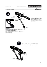
Page 70: ...position of the guide surfaces 9 Screw union nut with attached nozzle guard 9 to the gun body and make sure that the air cap horns lie in the designated recess Y 10 Before tightening with the air cap...

Page 71: ...71 B_03534 1 2 3 4 5 6 7 8 9 10 Y 11 1 OPERATING MANUAL EDITION 02 2016 ORDER NUMBER DOC 2366600...

Page 72: ...72 OPERATING MANUAL EDITION 02 2016 ORDER NUMBER DOC 2366600...

Page 73: ...zle guard 9 to the gun body and make sure that the air cap horns lie in the designated recess Y 9 Before tightening with the air cap horns Y set the desired jet level and then tighten the union nut to...

Page 74: ...ressure back on 10 Turn the trigger lock 14 to the spraying position and briefly pull the trigger 11 When the blockage has been flushed out secure the gun with trigger lock 14 12 Relieve pressure Chap...

Page 75: ...75 B_04790 9 10 11 X Y Y 1 14 12 12 OPERATING MANUAL EDITION 02 2016 ORDER NUMBER DOC 2366600 ACF5000 nozzle in cleaning position ACF5000 nozzle in spray position...

Page 76: ...600 7 3 11 VM 5020W CONTROL UNIT START UP 1 Turn switch to position 1 2 All LEDs on the control unit illuminate for approximately 1 second Hardware version Software version 3 The hardware version and...

Page 77: ...nce the recipe required has been called up the individual coating parameters can be called up and changed using the corresponding selection buttons see Chapters 7 3 13 7 3 14 When a parameter is chang...

Page 78: ...ocedure 1 Press the High voltage button 7 to adjust the high voltage The LED 8 indicates that high voltage is selected 2 The high voltage can now be adjusted using the universal rotary controller 2 be...

Page 79: ...n 10 100 A with a resolution of 1 A The corresponding value is indicated in the LED display 27 Above the Current Limitation button 5 is the Current Limitation bar graph display 22 If the control unit...

Page 80: ...The current actual value of the activated push button for the high voltage kV is digitally displayed on the LED display If the push button for the spray current limiter is pressed the relevant LED lig...

Page 81: ...DITION 02 2016 ORDER NUMBER DOC 2366600 7 3 16 STANDBY MODE Press push button 3 to return from this standby mode to the previously saved standby mode see figure below Note This function can be activat...

Page 82: ...Service Press the Service button 25 to go from the standby position of the control unit to the service menu display Structure of the service menu LED display 26 illuminates Push button Description of...

Page 83: ...push button R3 19 for a shorttime theLED 20 displaylightsup 3 Use the control dial 2 to set the maintenance interval limit you want e g 90 hours 4 Check setting in the LED display 27 5 The value is s...

Page 84: ...66600 7 3 19 CARRY OUT SERVICE DISPLAY Prerequisite The Service interval limit function is activated see Chapter 7 3 18 Service spray gun Once the time for the defined maintenance interval has expired...

Page 85: ...values can no longer be adjusted at the front control panel All recipe functions save call up recipe etc are locked C13 Lock off Lock is deactivated factory setting on Operating inhibit is activated Y...

Page 86: ...the Standby key 3 The Standby LED 4 lights up yellow 2 Press and hold the Service push button 25 3 Turn the universal control dial 2 with the other hand until the LED display 27 shows the number 10 Th...

Page 87: ...production sites or the WAGNER Service Center which have the necessary infrastructure 7 4 3 SETTING EXAMPLE PARAMETER C13 Group 1 Parameters C11 to C20 End user Group 2 Parameters C21 to C30 WAGNER S...

Page 88: ...L EDITION 02 2016 ORDER NUMBER DOC 2366600 The flashing LED display Service 26 indicates that the parameter value OFF in the display 27 can be changed by the universal control dial 2 Possible values f...

Page 89: ...ck diagram Chapter 5 5 4 This socket also offers the functions designated in the following illustration Before using it you have to select the respective parameters in the device configuration Control...

Page 90: ...value specification for spray current limitation Analog d c voltage input at pin 5 in reference to pin 8 ground 0 1 V corresponds to 1 A 10 0 V is a maximum specification and corresponds to 100 A 6 o...

Page 91: ...e shut down and locked to prevent it from being switched back on The spray gun must be separated from the high voltage supply before any cleaning work is started Only electrically conductive tanks may...

Page 92: ...terruptions Switch off the energy supply and the compressed air supply Relieve the pressure from the spray gun and device Secure the spray gun against actuation Observe the operating and service manua...

Page 93: ...the gun thoroughly as soon as clean flushing agent emerges 10 Relieve pressure Chapter 7 3 4 11 Remove flushing agent supply Blowing out the air passages of the spray gun 12 Close the pump pressure r...

Page 94: ...system into operation and check for leaks as described in Chapter 6 9 Carry out a function test if required in accordance with Chapter 11 According DGUV regulation 100 500 The liquid ejection devices...

Page 95: ...ack grounding bolt at the cabinet door below grounding switch on the RH side wall all cables and connections Monthly Door switch test Open the cabinet door Switch on the control unit Switch air on Act...

Page 96: ...ntal influences even when handled correctly Check hoses pipes and couplings every day and replace if necessary Before every commissioning check all connections for leaks Additionally the operator must...

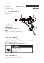
Page 97: ...ies Chapter 13 3 1 Push bared part of product hose approx 1 25 m 4 1 ft through the opening as far as the mounting plate 2 Fasten mounting plate 3 to grounding screw with knurled nut 2 3 Screw on stri...

Page 98: ...ximize the flow remove the nozzle open the dosing valve if necessary 2 Empty the pump in a controlled manner in accordance with pump s operating manual 3 Place the grounded collection tank under the i...

Page 99: ...ve Connect spray gun cable Spraygunnotconnectedordefective Contact the WAGNER Service Team Fault LED 24 lights up See the following table See the following table Fault message in display 27 DANGER Inc...

Page 100: ...replace gun cable Gun is not connected Check replace gun Connect gun E12 No coil current cascade interrupt The cascade is not connected Connect the cascade Cascade is interrupted Check or replace casc...

Page 101: ...duct pressure too high too low Adapt product pressure Damaged nozzle Attach new nozzle Poor wrap around Poor grounding at object Check grounding of object or hanger with ohmmeter Lacquer resistance to...

Page 102: ...3 Put the system into operation and check for leaks as described in Chapter 6 9 Function test in accordance with Chapter 11 According DGUV regulation 100 500 The liquid ejection devices should be chec...

Page 103: ...5263 Only as required Handle seal assembly tool Order No 2342334 not included in scope of delivery 10 3 MOUNTING MATERIALS In Chapter 14 the order numbers for device spare parts can be found as well a...

Page 104: ...x 25 B_05884 B_03537 SW3 SW12 SW12 OPERATING MANUAL EDITION 02 2016 ORDER NUMBER DOC 2366600 10 4 2 DISASSEMBLY OF THE SPRAY GUN Air hose When unscrewing the air hose a second open ended box wrench mu...

Page 105: ...e product hose but pull it straight out in the direction of arrow At the same time execute slight rotational movements Fitting 25 If the fitting 25 does not come out with the product hose it must be r...

Page 106: ...up the O ring and remove it Air distribution 9 1 Locate the start of the thread for recessed internal threading 2 Lever under the air distribution ring directly in front of the start of the thread us...

Page 107: ...es Spare parts may have safety relevant properties Only repair and replace parts that are listed in the Spare parts chapter and that are assigned to the unit Defective parts O rings and seal sets must...

Page 108: ...2 9992698 Vaseline white PHHV II 4 9992511 Loctite 243 Use Vaseline sparingly Only as required if the seal was removed press in using handle seal assembly tool Order No 2342334 not included in scope o...

Page 109: ...length adjusting measure X with withdrawal nut 7 and then fasten the threaded pin 6 using an Allen wrench SW2 Wear gloves The outside thread of the packing 9 must be free of lacquer Valve rod unit 8...

Page 110: ...osition Clamping screw assembly tool Order No 2325263 1 Move the valve rod to the rear position so that the sealing area does not become scratched 1 2 Slightly tighten AC valve tip 2 by hand 3 fingers...

Page 111: ...product hose check that no fitting 25 is in the gun adapter Check the fitting for damage and replace if necessary Order No 2338853 sparingly Ensure that the spring is inserted in the adapter Ensure th...

Page 112: ...rocess only exert counter pressure on the sleeve bracket and not on the entire cover 2 Position cover straight and level and carefully press in Use only minimal force gently rocking from side to side...

Page 113: ...02 2016 ORDER NUMBER DOC 2366600 Flat jet nozzle Diverse nozzle sizes see Chapter 13 2 Round jet nozzle Diverse nozzle sizes see Chapter 13 1 Air hose When screwing on the air hose a second open ende...

Page 114: ...ck the compressed air supply and decompress the system 3 Loosen and unscrew screw 2 4 Carefully remove control unit 3 forwards Pay attention to connecting lines and connecting cables at the back of th...

Page 115: ...l and Handle of the gun metal connections Pneumatic door switch Product hose connection Grounding switch Set value respective maximum 10 Check visually the black grounding band in the cabinet door inc...

Page 116: ...switch test The grounding switch must remain closed below 7 Test grounding switch Close cabinet door Air tap closed Remove gun The High voltage LED illuminates Voltage indicator 0 kV Current 80 100 A...

Page 117: ...1 2 PRODUCT PRESSURE TEST Exploding gas air mixture Danger to life from flying parts and burns Never spray into a closed tank Ground the tank DANGER 11 1 3 TEST OF SPRAY PATTERN Check spray pattern i...

Page 118: ...ith the household refuse but must be recycled in an environmentally correct manner WAGNER or one of our dealers will take back your used WAGNER electric or electronic equipment and will dispose of it...

Page 119: ...2309902 ACWR 5000 round jet nozzle adapter with nozzle spanner without AC round jet nozzle insert For details see Chapter 14 5 2 13 1 1 AIRCOAT ROUND JET NOZZLE INSERTS Order No Marking Jet width mm i...

Page 120: ...11 10 Synthetic resin lacquer 395211 11 20 20 PVC lacquers 395311 11 30 30 395411 11 40 40 395511 11 50 50 395611 11 60 60 395811 11 80 80 395113 13 10 0 33 0 013 10 Lacquers undercoat 395213 13 20 20...

Page 121: ...21 20 Mica paints 395421 21 40 40 Zinc rich paints 395521 21 50 50 Rust proofing paints 395621 21 60 60 Glue paints 395821 21 80 80 395423 23 40 0 58 0 023 40 395623 23 60 60 395823 23 80 80 395425 25...

Page 122: ...ft 4 1 2339157 Gun cable GM 5000E 10 m 32 81 ft 5 10 5 m 3676437 Protective hose mesh PP30 10 5 m 34 4 ft 15 m 49 2 ft Pos Stk Order No Designation 1 1 2339189 Hose set GM 5000EACW 15 m 49 2 ft Consis...

Page 123: ...sides only once at the product hose Fix the hose set within the protective hose approx once per meter by means of adhesive tape starting at distance E Note Cable ties are not permitted in areas C and...

Page 124: ...ng 2309368 Valve needle assembly tool 2325263 Clamping screw assembly tool 128901 Nozzle spanner ACR 2324766 Swivel joint air 259010 High voltage tester HV 200 N 999080 Wet film thickness gauge 50342...

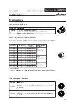
Page 125: ...n 353050 Hose holder 2359097 Gun holder For assembly on hose holder 353050 2326485 Wall mount GM 5000E left right 2359029 Underframe 5020 with rolls 2364394 Underframe 5010 with rolls 2364791 Tub inse...

Page 126: ...ormal mail express delivery air freight courier etc Identification in spare parts lists Explanation of column K labeling in the following spare parts lists Wearing parts Note These parts are not cover...

Page 127: ...asic device AquaCoat 2363292 2363734 2363401 2363736 2 1 Cabinet AquaCoat 3 1 Cabinet door AquaCoat 2367567 2367570 2367569 2367571 4 2 Hinge bolt 2358921 5 2 Securing ring 9922511 6 1 Instruction lab...

Page 128: ...992741 33 1 Double fitting G1 4 G1 4 9994627 34 1 Interlock lever 2358914 35 2 Grub screw 9901108 36 1 Spring rod 2366942 37 1 Tension spring 2362850 38 1 Driving pins 2358916 39 1 Pushrod welded 2358...

Page 129: ...129 B_05945 21 22 23 24 25 26 27 28 29 30 31 32 33 34 37 38 39 U 120 X Y X 51 25 24 54 52 53 W Y 61 62 63 64 25 65 66 65 64 65 30 35 36 121 OPERATING MANUAL EDITION 02 2016 ORDER NUMBER DOC 2366600...

Page 130: ...agon socket cylinder head screw 9907001 77 1 Hexagon socket cylinder head screw 9900325 78 1 Pressure spring 1 0x8 0 L 17 123357 79 3 Male stud elbow 6 1 8 Ex 9998110 80 2 Hexagon nut 9910106 81 1 Sho...

Page 131: ...No Order No Order No 101 2 m Hose black 10 mm 0 39 inch 9987076 102 1 9 m Hose black 8 mm 0 32 inch 9982078 103 3 7 m Hose black 6 mm 0 24 inch 9982079 104 3 4 m Strand yellow green 9953082 105 4 2 m...

Page 132: ...W CONTROL UNIT Spare parts list for VM 5020W control unit Pos K Stk Order No Designation 1 1 2362954 Control unit VM 5020W 2 1 Front panel VM 5000W 3 1 2304459 Incremental encoder type E33 4 1 2329441...

Page 133: ...G1 for 5x20 mm glass 14 1 Cable loom VM 5020W 15 2 9903306 Recessed head raised fillister head screw H form 16 1 9950330 Safety clip for device sockets 17 1 9920118 Washer 18 1 9910204 Self locking he...

Page 134: ...tion 31 3 9910103 Hexagon nut 32 7 9922011 Serrated lock washer externally toothed 33 1 2365967 Print VM 5020W rear panel complete Including connector plug and socket 34 3 263400 Distance bush 37 2 99...

Page 135: ...it Pos K Stk Order No Designation 41 5 2309112 Spacer 42 5 2312348 Hexagon lock nut 43 1 2317539 Print complete VM 5000 display Including pos 3 44 4 9903312 Recessed head raised fillister head screw H...

Page 136: ...fitting 8 mm 1 4 55 2 9998987 Threaded fitting 10 mm 1 4 56 3 9998677 Pressure gauge 0 10 bar RF40 d40 57 3 9992289 Male stud elbow 58 6 9900365 Hexagon socket cylinder head screw 59 12 9921511 Sprin...

Page 137: ...DOC 2366600 Spare parts list for VM 5020W control unit Pos K Stk Order No Designation 71 0 45 m 9987076 Hose black 10 mm 0 39 inch 72 0 30 m 9982078 Hose black 8 mm 0 32 inch 73 0 16 m 9982079 Hose b...

Page 138: ...DN25 B_05949 33 OPERATING MANUAL EDITION 02 2016 ORDER NUMBER DOC 2366600 14 3 PUMP SETS 14 3 1 PUMA 28 40 SET FOR AQUACOAT Remove fitting is not needed Air inlet behind the control unit Lubricate all...

Page 139: ...inder head screw 12 4 9921502 Spring washer 13 4 9920103 Washer Air motor connection 21 1 9999208 Male stud elbow 10 1 4 22 2 9985685 Reducing fitting A G1 2 I G1 4 23 1 2321426 Low pressure mini ball...

Page 140: ...2016 ORDER NUMBER DOC 2366600 14 3 2 COBRA 40 10 SET FOR AQUACOAT Air inlet behind the control unit Connection for potential equalization on the RH side wall Lubricate all stainless steel fittings wi...

Page 141: ...1 2353265 Fitting RF FM G1 4 G3 8 530 bar SSt 12 1 2329026 Inline filter HL DN6 PN530 G1 4 SSt For details see Chapter 14 3 5 13 1 2325826 Fitting DF MM G3 8 G1 4 530 bar SSt 14 1 2332865 HPP hose DN1...

Page 142: ...19 16 18 11 3 24 DN16 31 32 OPERATING MANUAL EDITION 02 2016 ORDER NUMBER DOC 2366600 14 3 3 EVOMOTION 20 30 SET FOR AQUACOAT Remove fitting is not needed Lubricate all stainless steel fittings with...

Page 143: ...s see Chapter 14 3 4 23 1 2329026 Inline filter HL DN6 PN530 G1 4 SSt For details see Chapter 14 3 5 24 1 2330774 Fitting DF MM G1 4 1 4NPSM 530 bar SSt Product inlet 31 1 2324110 Suction hose DN16 SS...

Page 144: ...combination 270 bar Pos K Stk Order No Designation 1 1 2329023 Relief combination 2 1 2324549 Relief housing 3 2 2323718 Hexagon plug 4 1 169248 Relief valve complete 5 1 2324552 Outlet pipe 6 1 3204...

Page 145: ...iddle 100 meshes per inch 1 2315723 Filter insert red fine 200 meshes per inch 10 pieces 1 2315724 Filter insert blue middle 150 meshes per inch 10 pieces 1 2315725 Filter insert yellow middle 100 mes...

Page 146: ...146 17 5 3 6 7 8 10 9 11 12 13 16 14 15 4 1 B_05970 20 25 18 22 OPERATING MANUAL EDITION 02 2016 ORDER NUMBER DOC 2366600 14 4 GM 5020EACW SPRAY GUN Dismantling and assembly see Chapter 10...

Page 147: ...1 2307104 Screw plug 11 1 2312180 Air regulation complete 12 1 9971182 O ring 13 1 9971182 O ring 14 1 2314360 Trigger 15 1 2307283 Cylindrical helical spring 16 2 2310617 Oval head screw with hexago...

Page 148: ...48 2 11 9 8 7 3 4 12 14 123 0 1 mm 15 10 6 1 B_05971 17 4 8425 0 004 inch 5 OPERATING MANUAL EDITION 02 2016 ORDER NUMBER DOC 2366600 14 4 1 GM 5020EACW ADAPTER Dismantling and assembly see Chapter 10...

Page 149: ...g AC complete 5 1 2312186 Valve needle AC complete 6 1 2362840 Adapter GM 5020EACW 7 1 9974166 O ring 8 1 2311562 Rod seal 9 1 2307062 Clamping screw valve rod 10 1 2313639 Valve rod unit AC 11 1 2357...

Page 150: ...150 7 1 B_04775 8 9 10 12 5 6 3 2 4 23 11 18 13 24 25 26 OPERATING MANUAL EDITION 02 2016 ORDER NUMBER DOC 2366600 14 4 2 GM 5000EAC HANDLE Dismantling and assembly see Chapter 10...

Page 151: ...2307290 Hose holder 5 1 2312182 Plug complete 6 1 2314270 Handle complete 7 1 2307232 Adapter seal 8 1 2311952 Stop screw 9 1 2309825 Oval head screw with hexagon socket 10 1 2310692 Seal 11 1 2311182...

Page 152: ...000 HV blue 3 1 2311777 Nozzle guard AC 4 1 2311776 Union nut AC 5 1 2311217 O ring sheathed Wearing part 14 5 2 ACR5000 ROUND JET NOZZLE ADAPTER Spare parts list round jet nozzle adapter EACW Pos K S...

Page 153: ...rame with rolls 2359029 2364394 2 2 Swivel castor support 3 2 Crossbar 4 4 Hexagon socket cylinder head screw 9900313 5 8 Washer 9920102 6 4 Self locking hexagon nut 9910208 7 4 Swivel castor with dou...

Page 154: ...e holder Pos K Stk Order No Designation 1 1 353050 Hose holder complete 3 3 9935049 Connection fields Wearing parts 14 5 5 GUN HOLDER Spare parts list for gun holder Pos K Stk Order No Designation 1 1...

Page 155: ...2 1 3207739 30 liter niveau compensator 3 1 9999435 T connection 4 4 9950615 Cable tie 5 1 3151777 Straight reduction 6 1 9999441 2 2 way valve 7 1 9943023 Adjustable check valve 8 1 R037 00 Pneumati...

Page 156: ...agitator With agitator Pos K Stk Designation Order No Order No 1 1 Drum cover D350 353054 353055 2 1 Cover 365 A with plug 2304618 3 1 Bushing 2367311 4 1 Agitator P300HS L400x16 D100 M32 2304533 5 1...

Page 157: ...han the address of the purchaser We do not provide warranty for damage that has been caused or contributed to for the following reasons Unsuitable or improper use faulty assembly or commissioning by t...

Page 158: ...EC Certificate of Conformity The CE certificate of conformity is enclosed with this product If needed further copies can be ordered through your WAGNER dealer by specifying the product name and serial...

Page 159: ......

Page 160: ...2366600 Edition 02 2016 Germany Phone Telefax E mail Switzerland Phone Telefax More contact addresses on the internet at Company Locations WAGNER worldwide Subject to changes without notice Document...

Reviews: