


29
AquaCoat GM 5000EACW
1
2
3
4
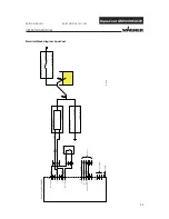
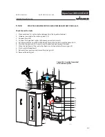
R1
R3
R2
B_03182
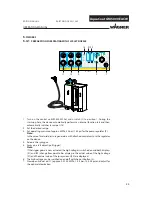
2
4
3
R1
R3
R2
E
B_03262
16
OPERATING MANUAL
EDITION 04/2012
PART NO. DOC2321362
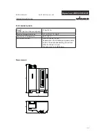
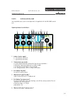
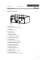
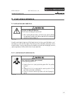
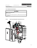
When the spray gun is connected to the control unit and the
control unit is switched on, the pre-defi ned recipe (R1, R2 or R3) is
shown on the gun display (2) as follows:
Recipe 1 ->
●❍❍❍❍
R1
Recipe 2 ->
●●●❍❍
R2
Recipe 3 ->
●●●●●
R3
Recipe change R1 -> R2 -> R3 -> R1.
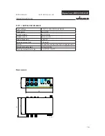
Press operating key (4) and keep pressed down for min. 2 seconds
to go forward one recipe.
Display (2) ->
●●❍❍❍
= recipe values temporarily changed:
If the operating key (4) is pressed for 2 seconds, the saved recipe
values for the previously selected recipes numbers will be
reloaded from the memory.
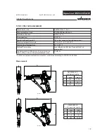
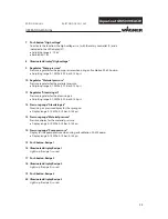
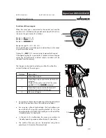
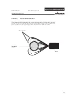
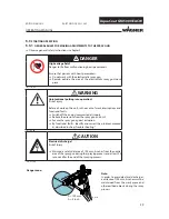
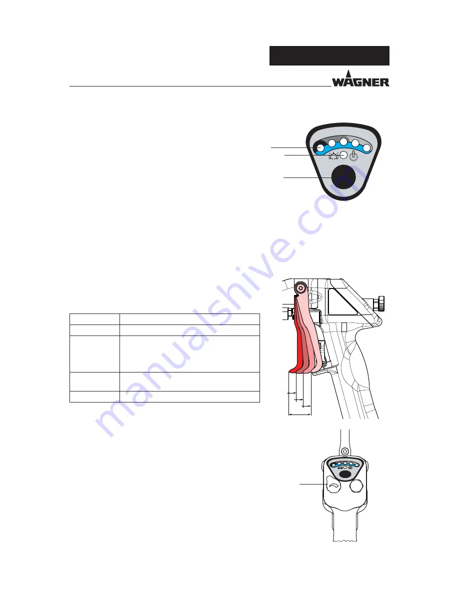
Functions of the spray gun
The trigger can be used to activate, one after the other, the
various functions of the spray gun.
Distance
Description
1
Atomizing air open
2
Atomizing air open and electrostatically (HV)
activated.
Display (2) for „spray current“ on the spray
gun
●❍❍❍❍
to
●●●●●
activated.
3
Atomizing air open, electrostatically (HV)
activated and material valve open
4
Max way of trigger
●
An increase in the tension needed to pull the trigger back will
be felt at the position where the material valve opens.
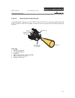
●
For spraying without high-voltage, the high-voltage can
be switched off using the operating button (4). Press the
operating button (4) briefl y: High-voltage is switched off. The
„standby display“ (3) illuminates.
●
In the event of a malfunction the spray gun switches to
“standby” operating mode and the display (3) illuminates.
●
The width of the spray jet can be adjusted using the air
adjustment (16) (only for fl at-jet method).
Summary of Contents for AquaCoat AirCoat GM 5000EACW
Page 2: ......
Page 38: ...38 AquaCoat GM 5000EACW OPERATING MANUAL EDITION 04 2012 PART NO DOC2321362 ...
Page 92: ...92 AquaCoat GM 5000EACW OPERATING MANUAL EDITION 04 2012 PART NO DOC2321362 ...
Page 101: ...101 AquaCoat GM 5000EACW OPERATING MANUAL EDITION 04 2012 PART NO DOC2321362 ...
Page 111: ......


