background image

60

AquaCoat GM 5000EACW 

OPERATING MANUAL

EDITION 04/2012

PART NO. DOC2321362

5.5 

DEVICE CONFIGURATION

5.5.1 

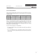
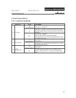
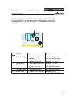
OVERVIEW OF PARAMETERS

Parameters

Value

Description

C13

User lock

off

(Factory setting)

User lock is switched off.

on

User lock is switched on: no target values (kV and µA) can 
be adjusted; you can only select the recipe and the control 
functions.

pro

User lock pro (program)
You can select recipes and control functions.
The target values (kV and µA) can be adjusted but cannot 
be saved in the recipes.

C19

Reset recipes

no

(Factory setting)

No reaction

res

All programs are set to delivery status when “res” is saved 
by the maintenance key.

C20

Reset 
confi guration

no

(Factory setting))

No reaction

res

All confi guration parameters are set to delivery status 
(factory setting) when “res” is saved by the maintenance 
key.

Summary of Contents for AquaCoat AirCoat GM 5000EACW

Page 1: ...izing air Mat Druckregler Mat pressure reg Pumpe Pump POWER 0 1 AquaCoat 1 B_03520 AquaCoat AirCoat EvoMotion 20 30S Wildcat 18 40 Puma 28 40 Cobra 40 10 AquaCoat AirCoat Spray system for non combustible spray media Edition 04 2012 Translation of the original Operating manual ...

Page 2: ......

Page 3: ...ility 10 3 2 Guarantee claim 10 3 3 CE Conformity 11 3 4 German regulations and guidelines 12 4 DESCRIPTION 13 4 1 Fields of application using in accordance with the instructions 13 4 1 1 Processable materials 13 4 2 Scope of delivery 14 4 2 1 Spraypack configuration 15 4 3 Technical data 17 4 3 1 Control unit VM 5000W 18 4 3 2 Spray gun GM 5000EACW 19 4 3 3 Pneumatic piston pump EvoMotion 20 30S ...

Page 4: ...flat jet nozzles 49 5 4 8 Cleaning of the nozzles 49 5 4 9 Eliminate nozzle clogging 49 5 4 10 Start up the control unit VM 5000W 51 5 4 11 Set and save recipes 52 5 4 12 Setting the high voltage 53 5 4 13 Setting the current limiting 54 5 4 14 Spray display 55 5 4 15 Standby Mode 56 5 4 16 Operating hours counter warning display 57 5 4 17 Maintenance display setup 58 5 4 18 Conduct service displa...

Page 5: ...11 3 Hoses and electrical cables 89 11 4 Miscellaneous 90 12 SPARE PARTS 93 12 1 How to order spare parts 93 12 2 Spare parts list AquaCoat Basic unit 94 12 2 1 Additional list of spare parts for variants with PP pump or Cobra 97 12 3 Spare parts list VM 5000W 98 12 4 Spare parts list GM 5000EACW 102 12 4 1 Spare parts list End piece GM 5000EACW 104 12 4 2 Spare parts list GM 5000EAC Handle 106 12...

Page 6: ...e can result in death serious injury and serious material damage Caution a possibly hazardous situation Non observance can result in minor injury Note provide information on particular characteristics and how to proceed Caution a possibly hazardous situation Non observance can cause material damage SIHI_0102_GB CAUTION This line warns of the hazard Possible consequences of failing to observe the w...

Page 7: ...ic in accordance with EN 61340 4 1 the resistance value may not exceed 100 MOhm Ensure that all persons within the working area wear antistatic shoes Footwear must comply with EN 20344 The measured insulation resistance may not exceed 100 MOhm Ensure that during spraying persons wear anti static gloves so that they are earthed via the handle of the spray gun If protective clothing is worn includin...

Page 8: ...mediately Avoid danger of injury through recoil forces Ensure that you have a firm footing when operating the spray gun Only hold the spray gun briefly in any one position Depending on the electrostatic charge and the flow speed of the spray an electrostatic charge may occur in the equipment This could cause a spark or flame on discharging Ensure that the unit is earthed for every spraying operation E...

Page 9: ...ssary For sufficient health and environmental safety Operate the unit in a spray booth or on a spraying wall with the ventilation extraction switched on Wear suitable protective clothing when working with hot materials Touch hot surfaces only if you are wearing protective gloves When operating the unit with a coating material with a temperature of 43 C 109 4 F Identify the unit with a warning label...

Page 10: ...ress of the purchaser We do not provide guarantee for damage that has been caused or contributed to for the following reasons Unsuitable or improper use faulty installation or commissioning by the purchaser or a third party normal wear negligent handling defective maintenance unsuitable coating products substitute materials and the action of chemical electro chemical or electrical agents except wh...

Page 11: ...declare that the supplied version of AquaCoat AirCoat GM 5000EACW Complies with the following guidelines 2006 42 EG 2006 95 EG 2002 96 EG 2004 108 EG 2002 95 EG Applied standards in particular DIN EN ISO 12100 1 2004 DIN EN ISO 12100 2 2004 DIN EN ISO 14121 2007 DIN EN 1953 2010 DIN EN 60204 1 2007 DIN EN 50059 1992 DIN EN 61000 6 2 2006 DIN EN 61000 6 4 2007 Applied national technical standards a...

Page 12: ...ng coating materials d BGR 104 Explosion protection rules e TRBS 2153 Avoiding ignition risks f BGR 180 Setting up for cleaning with solvents for cleaning workpieces with solvents g ZH 1 406 Guidelines for liquid ejection devices h BGI 740 Painting rooms and equipment j BGI 764 Electrostatic coating j Betr Sich V Plant Safety Ordinance Note All titles can be ordered from Heymanns Publishing House ...

Page 13: ...pray system The specific resistance of the spray material must be between 1k cm and 1M cm The following recipe can be used to determine whether the spray material is non flammable Gew H2 O 1 70 x Gew LM 0 96 x Gew ORG Where Gew Weight percent H2O Water LM Liquid organic phase solvent mainly consisting of higher ethylene glycol esters ORG Solid organic phase solids mainly consisting of binding agen...

Page 14: ...factory on the basis of the resulting configuration number The scope of delivery of each system includes Part No Description AquaCoat Spraypack consisting of AquaCoat cabinet Spray gun GM 5000EACW Control unit VM 5000W Pump Accessories 2310483 Operating manual German see Chapter 1 Operating manual in the local language Operating manual pump German Operating manual pump in the local language see Ch...

Page 15: ...h the following tables Model identification Pump Table A High pressure filter Table B Level monitoring Table C Barrel cover Agitator Table D Feed tank Table E Under frame Table F Hose holder Table G Hose set length Table H Nozzle Table I Air cap Table K Tables A B C D E F G H I K Examples 2327677 2 2 1 1 1 2 1 2 413 1 Configuration no 2327677 4 2 1 SPRAYPACK CONFIGURATION ...

Page 16: ... Description 1 no 2 yes Table H Hose set length No Type 1 7 5 m 24 6 ft 2 10 m 32 8 ft 3 15 m 49 2 ft 4 20 m 65 6 ft Table C Level monitoring No Description 1 no 2 yes Note for table I The complete Wagner nozzle range can be found in the accessories in Chapter 11 For flat jet nozzles the last 3 digits of the order number are used and for round jet nozzles the identification digits with preceding R...

Page 17: ...ON 04 2012 PART NO DOC2321362 Weight without paint container and pump 70 kg 154 lb Working temperature range 5 C 40 C 41 F 104 F Maxi material temperature 50 C 122 F Sound pressure level When the cabinet is open Dependent on the installed pump data can be found in the enclosed operating instructions When the cabinet is closed The values are 10 12 dB A lower 4 3 TECHNICAL DATA Measurements ...

Page 18: ...L EDITION 04 2012 PART NO DOC2321362 4 3 1 CONTROL UNIT VM 5000W Measurements Input voltage 115 V AC 230 V AC 50 Hz 60 Hz Input power max 40 W Output voltage max 20 Vpp Output current max 1 0 A AC High voltage limit 70 kV DC Spraying current limit 100 µA DC Polarity for positive and negative high voltage generator Weight without cables 6 2 kg 13 67 lb Working temperature range 5 40 C 41 104 F ...

Page 19: ... 116 psi Max material pressure 25 MPa 250 bar 3626 psi Material connection NPSM 1 4 18 Air connection G 1 4 A Weight without hose set 700 g incl union nut nozzle and air cap Working temperature range 5 C to 40 C 41 F to 104 F Maxi material temperature 50 C 122 F Material flow volume According to nozzle sizes See nozzle list on accessories Sound level at 0 3 MPa 3 bar 43 5 psi air pressure and 11 M...

Page 20: ...ALIAN 3PANISH ANISH 3WEDISH 0ORTUGUESE 4URKISH 2314783 2314784 2314785 2314786 2314787 2314788 2314790 2314789 2321572 4HIS OPERATING MANUAL IS AVAILABLE IN THE FOLLOWING LANGUAGES ANGUAGE 0ART O ANGUAGE 0ART O ERMAN NGLISH RENCH UTCH TALIAN 3PANISH ANISH 3WEDISH 0ORTUGUESE 4URKISH 367850 367851 367852 367853 367854 367855 367857 367856 367859 367858 4HIS OPERATING MANUAL IS AVAILABLE IN THE FOLLO...

Page 21: ...0 3 24 14 11 17 OPERATING MANUAL EDITION 04 2012 PART NO DOC2321362 4 4 FUNCTIONAL DESCRIPTION 4 4 1 DESIGN OF UNIT AND FUNCTION Pos Description 1 Cabinet AquaCoat assy 2 Front panel with 2 handles 3 Control unit VM 5000W 4 Spray gun GM 5000EACW 5 Hose set EACW 6 Material hose Filter discharge combination for spray gun 7 High voltage generator HV Cascade 8 Air inlet complete with ball valve 9 Inle...

Page 22: ...The following functions are provided for system safety The earthing switch 14 the door switch 17 the earthing strip 15 and the integrated AquaCoat resistor 19 Pos Description 10 Earthing cable 11 Material pressure generator such as pneumatic pump or double diaphragm pump 12 Suction system compl 13 Paint container 14 Earthing switch Cylinder AquaCoat 15 Earthing band 16 Filter relief combination 17...

Page 23: ...diagram AquaCoat Earthing Door switch Coil Coil Door switch Control unit VM 5000W Earth Earth monitoring Power supply brown green white Shield brown green yelllow white blue black white white Door switch Coil Coil Cascade AquaCoat Casting compound AquaCoat resistor Casting compound Earthing switch AquaCoat gelb grün Pneumatic cylinder yellow green Spray gun Dat dis Dat sw ...

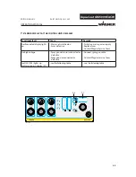
Page 24: ...supply 0 control unit switched off 1 control unit switched on 2 Universal rotary controller Dynamic digital rotary controller with 32 positions per revolution Adjustment speed is proportional to rotational speed Used to adjust high voltage and spray voltage For setting parameter values in configuration mode 3 Push button Standby To switch to stand by mode 4 Illuminated display Standby Lights up wh...

Page 25: ...psi 11 Regulator Atomizing air Pressure regulator for the atomizing air Adjusting range 0 1 0 MPa 0 10 bar 0 145 psi 12 Pressure gauge Atomizing air Atomizing air pressure display for the spray gun Display range 0 1 0 MPa 0 10 bar 0 145 psi 13 Pressure gauge Material pressure Pressure display for the material pressure Display range 0 1 0 MPa 0 10 bar 0 145 psi 14 Pressure gauge Pump pressure Displ...

Page 26: ...ay range 0 100 µA Single display Spraying current limit Bar display Actual spraying current 23 Illuminated display Door control Lights up when the front plate is fitting 24 Illuminated display Fault Lights up when a malfunction at the unit occurs 25 Press push button Service 26 Illuminated display Service 27 Display LED 7 segments three digit number Indicates the target and actual values of high v...

Page 27: ...65 OPERATING MANUAL EDITION 04 2012 PART NO DOC2321362 Connections on the rear side 28 Mains power input Connection for mains cable with safety clip 29 Primary fuse 1 0 ampere slow acting 30 Gun connection To connect a spray gun 31 High voltage connection Connection for high voltage generator 32 Cover of the service connections For Wagner service personnel only 33 Connection Pump air Hose connecto...

Page 28: ...tion against contact 6 Air cap for flat jet nozzle see chapter 11 2 7 Flat jet nozzle AFC5000 see chapter 11 2 2 8 Attachment 9 Cover 10 Handle Pos Description 11 Trigger lock 12 Trigger 13 Round jet nozzle cap see chapter 11 1 14 Round jet nozzle insert see accessories in chapter 11 1 1 15 Lock plug 16 Air adjustment 17 Electrical cable connection 18 Connection atomizing air 19 Material connectio...

Page 29: ...trigger can be used to activate one after the other the various functions of the spray gun Distance Description 1 Atomizing air open 2 Atomizing air open and electrostatically HV activated Display 2 for spray current on the spray gun to activated 3 Atomizing air open electrostatically HV activated and material valve open 4 Max way of trigger An increase in the tension needed to pull the trigger ba...

Page 30: ... atomize the material The air at 0 0 25 MPa 0 2 5 bar 0 36 psi produces a soft jet The size of the spray jet can be adjusted by turning the nozzle nut AirCoat air Multi channel swirl nozzle Spray jet Nozzle nut Spray material AirCoat air Advantages High painting capacity Low fogging tendency Good finish High viscosity paints can easily be applied High endurance of the nozzles Change in width the j...

Page 31: ...terial The AirCoat air at 0 0 25 MPa 0 2 5 bar 0 36 psi produces a soft jet which largely eliminates the problem of overlapping boundaries With shaping air the possibility exists of changing the jet spray width Shaping air Air cap Variable spray jet width Atomizing air Advantages High painting capacity Low fogging tendency Good finish High viscosity paints can easily be applied High endurance of t...

Page 32: ...lly charged in the system and atomized by the spray gun the paint particles are now transported by kinetic and electrostatic energy to the earthed work piece and adhere to the sprayed object finely distributed over the entire surface Paint particle Grounded object 4 4 1 2 3 THE ELECTROSTATIC EFFECT ...

Page 33: ...TILATION OF THE SPRAY BOOTH 5 1 INSTALLATION AND CONNECTION WARNING Incorrect installation operation Risk of injury and damage to equipment When putting into operation and for all work read and follow the operating instructions and safety regulations for the additionally required system components SIHI_0050_GB WARNING Toxic and or flammable vapor mixtures Risk of poisoning and burns Operate the un...

Page 34: ...hose bursting threaded joints Danger to life from injection of material Ensure that the hose material is chemically resistant Ensure that the spray gun threaded joints and material hose between the unit and the spray gun is suitable for the pressure generated in the unit Ensure that the following information can be seen on the high pressure hose Manufacturer Permissible operating pressure Date of ...

Page 35: ...d SIHI_0003_GB Earthing schema example Conveyor Spraying stand Floor derivable Object System earth 5 1 4 EARTHING System earth The imperfect earthing of a work piece will result in Very poor wrap around Uneven coating thickness Back spraying to the spray gun i e contamination The prerequisites for perfect earthing and coating are Clean work piece suspension Earthing of spray booth conveyor system ...

Page 36: ...l relevant components 5 1 5 2 INSPECTION OF THE SAFETY ELEMENTS Every day General visual inspection Earthing band all cables and connections for damage or loose contacts examine Monthly Door switch test Remove the front panel Switch on the control unit Actuate the trigger guard on the spray gun The high voltage must remain switched off Earthing cylinder test Insert front panel Switch on the contro...

Page 37: ...9 58 82 220 220 2 2 52 62 240 240 2 4 56 65 260 260 2 6 62 68 280 280 2 8 65 70 300 300 3 70 74 320 320 3 2 340 340 3 4 360 360 3 6 80 380 380 3 8 400 400 4 90 OPERATING MANUAL EDITION 04 2012 PART NO DOC2321362 The viscosity of the paints is of great importance The best results are obtained with paints between 25 and 40 DIN sec Measured in immersion flow cup DIN 4 mm 0 16 inch Processing of up to...

Page 38: ...38 AquaCoat GM 5000EACW OPERATING MANUAL EDITION 04 2012 PART NO DOC2321362 ...

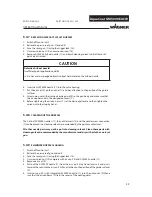
Page 39: ...on Risk of injury Before all work on the unit in the event of work interruptions and functional faults Switch off the energy compressed air supply Relieve the pressure from the spray gun and unit Secure the spray gun against actuation By functional faults Identify and correct the problem proceed as described in chap Trouble shooting Note In order to avoid electrical discharges a distance of 100 mm...

Page 40: ...1 13 23 15 7 5 12 26 22 6 20 16 19 2 4 8 9 10 3 24 14 11 17 OPERATING MANUAL EDITION 04 2012 PART NO DOC2321362 5 3 2 PREPARATION FOR STARTING UP 5 3 2 1 SPRAY PACK WITH PNEUMATIC PUMP EVOMOTION 20 30S CAUTION Impurities in the spraying system Spray gun blockage Flush the spray gun and paint supply with a suitable cleaning agent before putting into operation SIHI_0010_GB ...

Page 41: ...sure and secure the spray gun 4 10 Remove the detergent Start up for spraying 1 Fill the material container 13 with paint and place in the cabinet 2 Immerse in paint container the suction system 12 3 Clamp high voltage cable 22 to the metal paint container 13 or in the case of a plastic container to the metal part of the suction system 12 4 Connect the AquaCoat system to the electric socket with t...

Page 42: ...tainer 13 with suitable detergent into the AquaCoat cabinet 2 Immerse in container the suction system 12 3 Connect the earth 4 Connect the AquaCoat system to the compressed air source 8 5 Set a maximum pressure of 0 6 MPa 6 bar 87 psi on the control unit of the Cobra 40 10 6 Maintain the pressure for 5 minutes and check all connecting parts for leaks 7 When the tightness of the system has been asc...

Page 43: ... Clamp high voltage cable 22 to the metal paint container 13 or in the case of a plastic container to the metal part of the suction system 12 4 Connect the AquaCoat system to the electric socket with the electric cable 9 5 Insert front panel 2 6 Switch on mains switch on the VM 5000W 7 The system is ready for use SIHI_0130_GB CAUTION Electrical discharge when using coated material containers Risk ...

Page 44: ...omatically switches to recipe 1 15 2 Set the desired recipe 3 Set operating pressure of approx 8 MPa 80 bar 1160 psi for the pump regulator 9 Note In the case of material pressure generators with attached control unit use the regulator on the device 4 Release the spray gun 5 Spray on a test object pull trigger Note If the trigger guard is now actuated the high voltage is switched on and both displ...

Page 45: ...he air adjustment at the back of the gun does not affect the spray pattern in this process For flat jet method 6 Change the width of the spray jet by turning the air adjustmentbacktothespraygunorbyappropriateselection of the nozzle 1 Secure gun and place the appropriate nozzle 2 Switch on the pump adjust from approx 8 MPa 80 bar 1160 psi and the control unit 3 Spray pull trigger 4 Adjust the spray...

Page 46: ... shown in the figure below 5 With the air adjustment on the gun the ratio form adjustement to atomization until the optimum spray pattern is achieved Note Repeat point 4 and 5 until the optimum spray pattern is reached process iterative Closed air adjust ment Completely opened air adjustment Influence of the air adjustment on the spray pattern shape The spray pattern can be adjusted to suit the ob...

Page 47: ...GED ROUND JET NOZZLES 1 Remove nozzle insert 1 using nozzle spanner 2 2 Fit the new nozzle insert 1 By means of nozzle spanner 2 loosen nozzle insert 1 by a half turn 2 Remove the nozzle spanner and briefly actuate trigger guard 3 After cleaning the nozzle re tighten the nozzle insert 5 4 5 EXCHANGE OF ROUND JET NOZZLE INSERT ...

Page 48: ... nozzle insert 3 using nozzle spanner 4 6 Unscrew nozzle nut 5 and remove nozzle screw connection 7 and sealing nipple 8 out off the nozzle body 6 and clean all parts thoroughly 7 Insert desired ACF5000 nozzle 11 into the valve housing 8 Put the air cap 10 on the nozzle 11 and pay attention to the position of the guide surfaces 9 Screw union nut with attached nozzle guard 9 to the gun body and mak...

Page 49: ...s 3 and the nozzle screw connection 7 can be placed in a cleaning solvent recommended by the paint manufacturer All other nozzle parts may not be put into cleaning solvent Clean these parts with cleaning solvent recommended by the manufacturer and dry with a cloth or a air jet gun CAUTION Defective AirCoat nozzle Insufficient paint application quality Do not use sharp edged objects to treat hard me...

Page 50: ...veaircap 10 andputACF5000nozzle 11 outoffaircapbyhand CleanACF5000 nozzle and insert it in spraying position into the valve housing 14 Put the air cap 10 on the nozzle 11 and pay attention to the position of the guide surfaces X 15 Screw union nut with attached nozzle guard 9 to the gun body and make sure that the air cap horns lie in the designated recess Y 16 Before tightening the air cap horns ...

Page 51: ...NO DOC2321362 5 4 10START UP THE CONTROL UNIT VM 5000W 1 Turn switch to position 1 2 All LEDs on the control unit illuminate for approx 1 second Hardware version Software version 3 The hardware version and the software version are shown on the display alternately in succession 4 After a few seconds the control unit is ready for operation Note Each start process is concluded by allocating the saved...

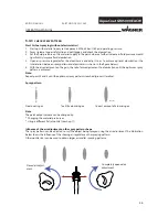
Page 52: ...m buttons R1 R2 and R3 Once the recipe required has been called up the individual coating parameters can be called up and changed using the corresponding selection buttons see chapter 5 4 7 and 5 4 8 When a parameter is changed the LED on the left of the program button flashes to indicate that a parameter value has been changed The process for saving parameters is described below To reuse the orig...

Page 53: ...IGH VOLTAGE Works procedure 1 Press the High voltage button 7 to adjust the high voltage The LED 8 indicates that high voltage is selected 2 The high voltage can now be adjusted using the universal rotary controller 2 between 5 to 70 kV with a resolution of 1 kV The value is shown in the LED display 27 Above the High voltage button 7 is the High voltage bar graph display 21 When the control unit i...

Page 54: ...ng the universal rotary controller 2 between 10 100 µA with a resolution of 1 µA The value is shown in the LED display 27 Above the current limiting button 5 is the Current limiting bar graph display 22 When the control unit is in the ready position this display shows the set point as a dot The current limiting is an adjustable threshold If this threshold is exceeded for example by approach of the...

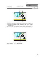
Page 55: ...e current actual value of the activated pushbutton for the high voltage kV is digitally displayed on the LED display If the pushbutton for the spray current limiter is pressed the relevant LED lights up and the corresponding actual value in µA appears in the LED display Ready to spray using R2 recipe see picture below Control unit in standby position The nominal value LEDs illuminate as dots and t...

Page 56: ...PERATING MANUAL EDITION 04 2012 PART NO DOC2321362 5 4 15STANDBY MODE Press pushbutton 3 to return from this standby mode to the previously saved standby mode see figure below Note This function can be activated and used from the gun If you want to spray without high voltage select standby mode Briefly press the Standby pushbutton 3 LED 4 will illuminate All other LEDs are extinguished ...

Page 57: ...red for the spray gun Press the Service button 25 to go from the standby position of the control unit to the maintenance menu display Structure of the maintenance menu LED display 26 illuminates Push button Description of display R1 Display of absolute accrued operating hours of the spray gun Display format Counter status 999 hours 001 1 hour 291 291 hours Counter status 1000 hour 1 23 1230 hours ...

Page 58: ...dure 1 Actuate the push button R3 19 for a short time the LED 20 display lights up 2 Use the dial 2 to set the maintenance interval limit you want e g 90 hours 3 Check setting in the LED display 27 4 The value is saved by pressing down the Spray current pushbutton 5 until the LED display 27 starts to flash Works procedure 1 Actuate the push button R2 17 for a short time the LED 18 display lights u...

Page 59: ...ART NO DOC2321362 5 4 18 CONDUCT SERVICE DISPLAY Prerequisite The function maintenance interval limit is activated Conduct service on spray gun Once the time for the defined maintenance interval has expired the LED display 26 starts to flash The flashing service display merely acts as a warning You can continue working without any limitations ...

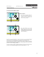
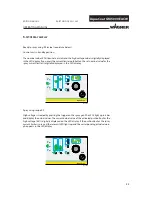
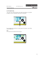
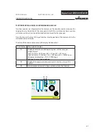
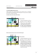
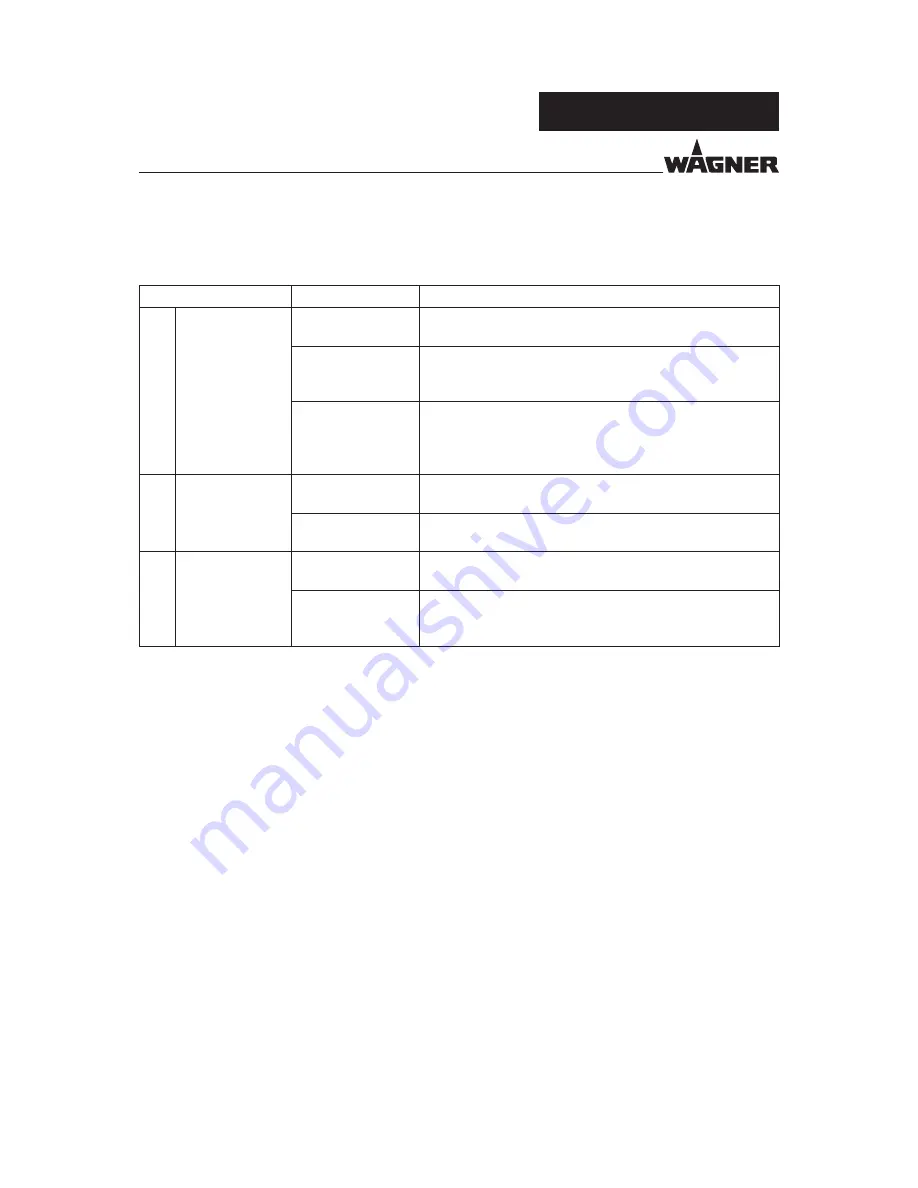
Page 60: ...ly select the recipe and the control functions pro User lock pro program You can select recipes and control functions The target values kV and µA can be adjusted but cannot be saved in the recipes C19 Reset recipes no Factory setting No reaction res All programs are set to delivery status when res is saved by the maintenance key C20 Reset configuration no Factory setting No reaction res All config...

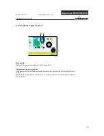
Page 61: ...pressing the Standby key 3 The Standby LED 4 lights up yellow 2 Press push button Service 25 and hold it down 3 Turn the universal control dial 2 with the other hand until the LED display 27 shows the number 10 Then release button Service 25 The running text configuration is displayed in the LED display 27 The device is now in configuration mode 4 The first configuration parameter C11 is now displ...

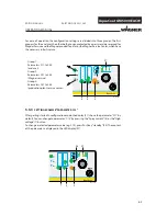
Page 62: ...rved for Wagner Service and theWagner production sites or theWagner Service Center which have the necessary infrastructure Group 1 Parameters C11 to C20 end user Group 2 Parameters C21 to C30 Wagner service Group 3 Parameters C31 to C40 production plant service center 5 5 3 SETTING EXAMPLE PARAMETER C13 After getting started in configuration mode the display 27 shows the parameter C11 by default Y...

Page 63: ...1 3 OPERATING MANUAL EDITION 04 2012 PART NO DOC2321362 The flashing LED display maintenance 26 indicates that the parameter value OFF in the display 27 can be changed by the universal control dial 2 Possible values for parameter C13 are on off or pro Keep the Push button maintenance 25 held down to have the set value saved to parameter C13 Press the Standby key 3 to exit configuration mode ...

Page 64: ...n seals Never immerse the spray gun in cleaning agent or water SIHI_0002_GB SIHI_0004_GB WARNING Incorrect maintenance repair Risk of injury and damage to the equipment Repairs and part replacement may only be carried out by specially trained staff or a WAGNER service center Before all work on the unit and in the event of work interruptions Switch off the energy compressed air supply Relieve the p...

Page 65: ...ith a cloth or blow gun With flat jet nozzle fitted 5 Remove AirCoat nozzle and clean separately see chapter 5 4 7 6 Actuate the trigger guard Flush the gun through thoroughly 7 Relieve the pressure of gun and unit 8 Clean the spray gun body with a cleaning agent recommended by the manufacturer and dry with a cloth or blow gun 6 1 FINISHING WORK AND CLEANING SIHI_0145_GB CAUTION Cleaning agent in ...

Page 66: ... instructions when carrying out all work Functional fault Cause Remedy Insufficient material output Nozzle too small Flat jet Select larger nozzle see nozzle table Material pressure too low Increase material pressure Material viscosity too high Thin material in accordance with the manufacturer s instructions Filter in material supply clogged Clean or replace filter Nozzle is clogged Clean or repla...

Page 67: ...ressure Back spraying Object not earthed Check earthing Distance between spray gun and object too large Reduce distance between spray gun and object High voltage set wrongly too high Adapt high voltage to material No wrap around No high voltage Repair malfunction as laid down in the control unit operating instructions Seal in end piece defective Repair by Wagner Service Center Air passages damp Cl...

Page 68: ... AT THE CONTROL UNIT VM 5000W Functional fault Cause Remedy No illuminated display lights up Mains not switched on Fuses defective Switch on mains power supply Replace fuses Contact Wagner Service Team No high voltage Spray gun cable not connected or defective Spray gun not connected or defective Connect spray gun cable Contact Wagner Service Team Fault LED 24 lights up Fault message in display 27...

Page 69: ...has been remedied and acknowledged with push button service 25 Code Display Malfunction Cause Remedy E11 Earth monitoring The grounding cable is interrupted The gun is not connected Check replace gun cable Check or replace spray gun Connect the spray gun E12 No coil current Cascade interrupt The cascade is not connected Cascade is interrupted defective Connect the cascade Check or replace cascade ...

Page 70: ...itably trained person may carry out repairs and replace parts Only repair and replace parts that are listed in the chapter Spare parts catalog Before all work on the unit and in the event of work interruptions Disconnect the control unit from the mains Relieve the pressure from the spray gun and unit Secure the spray gun against actuation Observe the operating and service instructions when carryin...

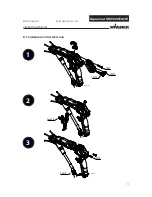
Page 71: ...71 AquaCoat GM 5000EACW 1 2 3 B_03537 SW3 SW12 SW12 SW3 SW19 Torx 25 B_03538 OPERATING MANUAL EDITION 04 2012 PART NO DOC2321362 8 1 DISMANTLING OF THE SPRAY GUN ...

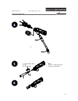
Page 72: ...Coat GM 5000EACW B_03539 SW19 SW19 4 5 6 B_03556 SW9 OPERATING MANUAL EDITION 04 2012 PART NO DOC2321362 Assembly tool for need le valve Part No 2309368 Note Loosen AC valve tip by hand using an assembly tool ...

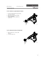
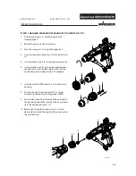
Page 73: ... 3 Unscrew the complete package 3 via valve rod unit 2 6 7 or pull out the valve rod unit and unscrew it using an Allen key SW5 4 If the loosened package 3 in the hole jammed emit from the front 1 Undo the oval head screw 1 2 Pull the air valve out off the hole Removing air valve Hold the piston rear 2 and unscrew piston front SW6 Removing air valve Unscrew and remove the sealing nut SW8 Hold the ...

Page 74: ...e should be taken that these parts remain free of solvents grease or sweat from the hands salt water Spare parts may have safety relevant properties Defective parts O rings and seal sets must always be re placed In chapter 12 can be found part numbers for gun spare parts as well as for wearing parts such as seals WARNING Incompatibility of cleaning agent and working medium Risk of explosion and da...

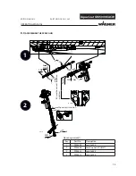
Page 75: ...ERATING MANUAL EDITION 04 2012 PART NO DOC2321362 8 3 ASSEMBLING THE SPRAY GUN Ensure the correct insertion position Ensure the correct insertion position Mounting materials Pos Part No Description 1 9992590 Loctite 222 2 9992698 Vaseline weiss PHHV II 3 9992831 Loctite 542 4 9992511 Loctite 243 ...

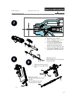
Page 76: ...eaded pin SW2 Push together the valve rod unit and the compl package Screw in together the valve rod unit and the compl package Remove the valve rod unit Tighten the compl package Carefully insert the valve rod unit and mount with an assembly tool 5 the clamping screw assy 1 Tighten slightly AC valve tip by hand using an assembly tool Part No 2309368 Ensure the correct insertion position Note Asse...

Page 77: ...77 AquaCoat GM 5000EACW 6 7 8 B_03540 SW19 2 5 Nm SW3 SW19 B_03541 Torx 25 B_03542 OPERATING MANUAL EDITION 04 2012 PART NO DOC2321362 Push the trigger upward into the air valve piston ...

Page 78: ...3 0 8 Nm SW12 SW12 2 OPERATING MANUAL EDITION 04 2012 PART NO DOC2321362 Flat jet nozzle Assembly see chapter 12 5 1 Diverse nozzle sizes see chapter 11 2 Round jet nozzle Assembly see chapter 12 5 2 Diverse nozzle sizes see chapter 11 1 Einbaulage beachten ...

Page 79: ...ITION 04 2012 PART NO DOC2321362 8 4 REPLACING THE SPRAY GUN INCLUDING HOSE SET Disassembling gun assy 1 1 Loosen the union nut 6 on the bared part of the material hose 3 with a universal spanner 2 Loosen the knurled nut on the gun cable 5 and remove connector 3 Loosen the union nut 4 of the air hose at the AquaCoat cabinet 4 Unscrew knurled nut 2 5 Carefully remove the gun 1 together with the hos...

Page 80: ...3 Fix mounting plate 3 to earthing screw with knurled nut 2 4 Screw air hose for the spray gun 4 to the AquaCoat cabinet 5 Connect gun cable 5 to AquaCoat cabinet and secure with screw 6 Screw bared end of material hose 3 with union nut 6 to relief combination 8 5 CHANGE MATERIAL HOSE AND OR AIR HOSE 1 Loosen and unscrew clamping screw 1 2 Loosen nut 2 and remove material hose from the attachment ...

Page 81: ... OPERATING MANUAL EDITION 04 2012 PART NO DOC2321362 8 6 DISASSEMBLING CONTROL UNIT VM 5000W 1 Switch off the control unit and remove the front panel 1 2 Close the compressedair connection and relieve the system pressure 3 Loosen and unscrew screw 2 4 Carefully remove control unit 3 forwards Pay attention to connecting lines and connecting cables at the back of the control unit ...

Page 82: ... m pe Pu m p P O W ER 0 1 1 2 B_03533 OPERATING MANUAL EDITION 04 2012 PART NO DOC2321362 8 7 OPENING THE CONTROL UNIT 1 Dismount control unit from the AquaCoat system see Chap 8 6 2 Place control unit on a suitable surface 3 Loosen and unscrew screw 1 4 Remove cover 2 from housing 5 When the repair is complete replace the cover 2 on the housing and fix with the screws 1 ...

Page 83: ...ce between earth terminal and handle of the gun metal fittings Set value max 10 Check resistance between earth terminal and earthing band Set value max 10 Multi meter 3 Connect the device Connect earthing cable Main tap closed Connect air supply mains pressure 0 8 MPa 8 bar 116 psi Connect the mains 4 Adjust horn only for level indication with horn Loosen control unit and remove from mounting see ...

Page 84: ...n switch off Air on Main switch on door locked Main switch off door unlocks 8 Test spraying Fit door Main switch on Set high voltage to 5 kV Remove gun With the gun removed gradually increase the high voltage up to maximum voltage 70 kV No more than one LED must illuminate on the current indicator 10µA Main switch off ...

Page 85: ... the disposal of waste electrical equipment and its implementation in national law this product may not be disposed of with the household refuse but must rather be recycled in an environmentally correct manner Your waste Wagner electrical device will be taken back by us or our representatives and disposed of environmentally correctly Please contact one of our service points or one of our represent...

Page 86: ...d jet nozzles are especially suited to spray pipes profiles and complex workpieces Standard Jet width in mm inches at a distance of 30 cm 11 8 inches from the object and at a pressure of 10 MPa 100 bar 1450 psi Part No Description 2309901 LV air cap compl suitable for low viscosity materials marked red 2314204 HV air cap compl suitable for high viscosity materials marked blue 11 2 ACF AIR CAPS FLA...

Page 87: ... 13 80 0 33 0 013 10 20 30 40 50 60 80 395115 395215 395315 395415 395515 395615 395815 15 10 15 20 15 30 15 40 15 50 15 60 15 80 0 38 0 015 10 20 30 40 50 60 80 395217 395317 395417 395517 395617 395817 17 20 17 30 17 40 17 50 17 60 17 80 0 43 0 017 20 30 40 50 60 80 B_03163 OPERATING MANUAL EDITION 04 2012 PART NO DOC2321362 11 2 1ACF5000 AIRCOAT FLAT JET NOZZLES Part No Marking Diameter of bore...

Page 88: ...395625 395825 25 40 25 60 25 80 0 64 0 025 40 60 80 395427 395627 395827 27 40 27 60 27 80 0 69 0 027 40 60 80 395429 395629 395829 29 40 29 60 29 80 0 75 0 029 40 60 80 395431 395631 395831 31 40 31 60 31 80 0 79 0 031 40 60 80 395435 395635 395835 35 40 35 60 35 80 0 90 0 035 40 60 80 OPERATING MANUAL EDITION 04 2012 PART NO DOC2321362 mm inch Rust proofing paint Latex paint Mica paint Zinc dust...

Page 89: ...32 81 ft 4 1 2307293 Gun cable GM 5000E 10 m 32 81 ft 5 9 5m 3676437 PP30 protective hose mesh 9 5 m 31 17 ft Pos Qty Part No Description 1 1 2309867 Hose set GM 5000EACW 15 m 49 2 ft Consisting of 2 1 2309888 Material hose EACW assy 15 m 49 2 ft 3 1 2310501 Air hose assy 15 m 49 2 ft 4 1 2309474 Gun cable GM 5000E 15 m 49 2 ft 5 14 5m 3676437 PP30 protective hose mesh 14 5 m 47 57 ft Pos Qty Part...

Page 90: ...O DOC2321362 11 4 MISCELLANEOUS Part No Description 353702 Insulating oil 10 ml 10 cc 9992511 Loctite 243 50 ml 50 cc 9992590 Loctite 222 50 ml 50 cc 2309368 Assembly tool valve needle 128901 Nozzle spanner ACR 2325263 Assembly tool clamping screw 2324766 Swivel Air 2319653 Protective gun coating ...

Page 91: ...ANUAL EDITION 04 2012 PART NO DOC2321362 Part No Description 259010 High voltage tester HV 200 N 999080 Wet film thickness measurer 50342 Viscosity cup DIN 4 353050 Hose holder assy 353051 Base frame assy 353052 Feed tank 2326485 Wall mount GM 5000E left right ...

Page 92: ...92 AquaCoat GM 5000EACW OPERATING MANUAL EDITION 04 2012 PART NO DOC2321362 ...

Page 93: ...t all work Always supply the following information to ensure delivery of the right spare part Part Number description and quantity The quantity need not be the same as the number given in the Quantity column This number merely indicates how many of the respective parts are used in each sub assembly The following information is also required to ensure smooth processing of your order Address for the...

Page 94: ...quaCoat 15 1 9999208 Angle screwing in connection G1 4 16 2 9900308 Cheese head screw with hexagon 17 1 9900315 Cheese head screw with hexagon 18 1 9900346 Cheese head screw with hexagon 19 2 9910102 Hexagon nut M6 21 2 9910204 Hexagon nut with clamp 22 1 9911008 Hexagon nut flat 23 3 9920103 Serrated lock washer A6 4 24 8 9920118 Washer 25 4 9922109 Serrated washer 27 1 9952558 Warning sign High ...

Page 95: ...uckregl er Mat pressure reg Pumpe Pump POWER 0 1 AquaCoat 52 D 50 51 54 6 14 27 15 33 3 7 29 8 10 9 16 5 31 32 2 1 46 57 B_03391 18 24 28 24 25 A 17 23 24 25 24 21 B 13 23 19 25 24 24 21 C 40 24 24 23 19 25 41 42 43 D 44 4 55 56 45 12 53 22 11 30 A C 58 OPERATING MANUAL EDITION 04 2012 PART NO DOC2321362 View E from out ...

Page 96: ...rotection Class Norm Standard EN 50059 IP 54 Spannung Voltage Strom Current max 18Vpp max 1 0A B_03514 48 49 OPERATING MANUAL EDITION 04 2012 PART NO DOC2321362 Spare parts list AquaCoat Pos K Qty Part No Description 47 1 353523 Retainer 48 1 2314160 Connection gun cable VM 5000W 49 1 2314159 Control cable VM 5000W 50 1 353867 Front plate assy 51 1 353504 Sticker AquaCoat 52 1 353866 Cabinet AquaC...

Page 97: ...2321362 Pos K Qty Part No Description 1 353870 Air hose AC assy 1 1 9985619 Hose nozzle with sealing ring 2 2 9990404 Hose clips 3 1 9981951 Hose 1 2 m 3 94 ft 4 1 9998812 Quick coupling with hose nozzle Wearing part 12 2 1ADDITIONAL LIST OF SPARE PARTS FORVARIANTSWITH PP PUMP OR COBRA ...

Page 98: ...856 Enlarging connector from 8 mm 0 31 inches to 10 mm 0 39 inches 21 1 9900338 Cheese head screw with hexagon 22 2 9903306 Oval head screw 23 2 9903311 Oval head screw 24 4 9903312 Oval head screw 25 6 9907010 Countersunk screw 26 1 9910102 Hexagon nut 27 3 9910103 Hexagon nut 28 1 9910204 Hexagon nut 29 4 9920118 Washer 30 7 9922011 Lock washer outside toothed 31 2 9922109 Serrated washer inside...

Page 99: ...99 AquaCoat GM 5000EACW B_03515 6x 42 48 1 43 20 8 9 52 51 45 50 54 33 6 25 27 4 18 38 30 24 17 11 7 19 12 40 53 44 41 21 31 29 A B 36 35 18 18 41 OPERATING MANUAL EDITION 04 2012 PART NO DOC2321362 ...

Page 100: ...ription 43 3 9992743 Screw in screw connection straight 44 1 9998157 Loctite 480 45 2 9998253 Screw in angle 46 1 9998614 Straight bulkhead plug in connection 47 2 9998615 Straight bulkhead plug in connection 48 3 9998677 Pressure gauge 0 1 MPa 0 10 bar 0 145 psi d40 49 2 9998769 Straight bulkhead plug in connection 50 1 9999208 Angle screwing in connection 51 1 9999224 Pressure regulator 52 2 999...

Page 101: ...101 AquaCoat GM 5000EACW OPERATING MANUAL EDITION 04 2012 PART NO DOC2321362 ...

Page 102: ...102 AquaCoat GM 5000EACW 17 5 3 6 7 8 10 9 11 12 13 16 14 15 4 2 18 1 B_03548 20 OPERATING MANUAL EDITION 04 2012 PART NO DOC2321362 12 4 SPARE PARTS LIST GM 5000EACW ...

Page 103: ...9900386 Cheese head screw with hexagon 9 1 2311970 Sealing plug 10 1 2307104 Lock screw 11 1 2312180 Air regulation compl 12 1 9971182 O ring 13 1 9971182 O ring 14 1 2314360 Trigger 15 1 2307283 Cylindrical helical spring 16 2 2310617 Oval head screw with hexagon 17 1 2309468 Material hose EACW assy 7 5 m 24 6 ft 17 1 2309887 Material hose EACW assy 10 m 32 81 ft 17 1 2309888 Material hose EACW a...

Page 104: ...uaCoat GM 5000EACW 2 1 11 9 8 7 3 4 5 12 13 14 123 0 1 15 10 16 6 B_03549 OPERATING MANUAL EDITION 04 2012 PART NO DOC2321362 12 4 1SPARE PARTS LIST END PIECE GM 5000EACW Ensure the correct insertion position ...

Page 105: ... 4 1 2312175 Valve housing AC assy 5 1 2312186 Valve tip AC assy 6 1 2314272 GM 5000EAC end piece 7 1 9974166 O ring 8 1 2307062 Clamping screw valve rod 9 1 2311562 Rod seal 10 1 2313639 Valve rod unit AC 11 1 2312178 Packing assy 12 1 2311624 O ring 13 1 2307051 Clamping screw package 14 1 2307059 Withdrawal nut 15 1 9901411 Threaded pin with hexagon 16 1 2320256 O ring 1 2326392 Service set GM ...

Page 106: ...106 AquaCoat GM 5000EACW 20 16 17 18 19 15 25 26 14 24 13 7 1 B_03165 8 9 10 12 5 6 3 2 4 23 11 OPERATING MANUAL EDITION 04 2012 PART NO DOC2321362 12 4 2SPARE PARTS LIST GM 5000EAC HANDLE ...

Page 107: ...val head screw with hexagon 10 1 2310692 Seal 11 1 2311182 Straight pin 12 1 2309400 Safety clip 13 1 2312189 Air valve 14 1 2307557 Seal 15 1 2307935 Piston front 16 1 2312846 Cylindrical helical spring 17 1 2310680 Sleeve 18 1 9974218 O ring 19 1 2310682 Seal 20 1 2316246 Piston compl 23 1 9974166 O ring 24 1 2303437 O ring 25 1 2325291 Sealing nut 26 1 2325294 Washer Air valve 1 2326392 Service...

Page 108: ...S LISTS ACCESSORIES 12 5 1SPARE PARTS LIST FLAT JET NOZZLES Flat jet nozzles spare parts list Pos K Qty Part No Description 1 1 2315775 Union nut AC assy 2 1 2309901 Air cap LV EACW red 2 1 2314204 Air cap HV EACW bue 3 1 2311777 Nozzle guard AC 4 1 2311776 Union nut AC 5 1 2311217 O ring sheathed Wearing part ...

Page 109: ...are parts list Round jet nozzle cap EACW Pos K Qty Part No Description 1 1 2309902 Round jet nozzle cap ACWR 5000 2 1 2307220 Nozzle nut 3 1 2315310 O ring 4 1 132351 Nozzle screwed connection holder 5 1 2307219 Nozzle body 9 1 132516 Nozzle screwed connection complete 10 1 2307216 Sealing nipple 11 1 2311217 O ring 12 1 128901 Nozzle spanner assy Wearing part ...

Page 110: ...trielles wagner france fr Netherlands WSB Finishing Equipment B V De Heldinnenlaan 200 NL 3543 MB Utrecht Telephone 31 0 30 241 4155 Telefax 31 0 30 241 1787 E Mail info wsb wagner nl HP www wsb wagner eu Italy WAGNER COLORA S r l Via Fermi 3 I 20875 Burago di Molgora MB Telephone 39 039 625021 Telefax 39 039 6851800 E Mail info wagnercolora com Japan WAGNER Spraytech Ltd 2 35 Shinden Nishimachi J...

Page 111: ......
Page 112: ...RMANY 7 2 MB TTO ILIENTHAL 3TR 0OSTFACH ARKDORF 4ELEPHONE 4ELEFAX AIL SERVICE STANDARD WAGNER GROUP COM 3WITZERLAND 7 2 NDUSTRIESTRASSE 0OSTFACH LTSTËTTEN 4ELEPHONE 4ELEFAX AIL REP CH WAGNER GROUP CH WWW WAGNER GROUP COM 2321362 ...

Reviews: