background image

21

Control Pro 250 M

GB

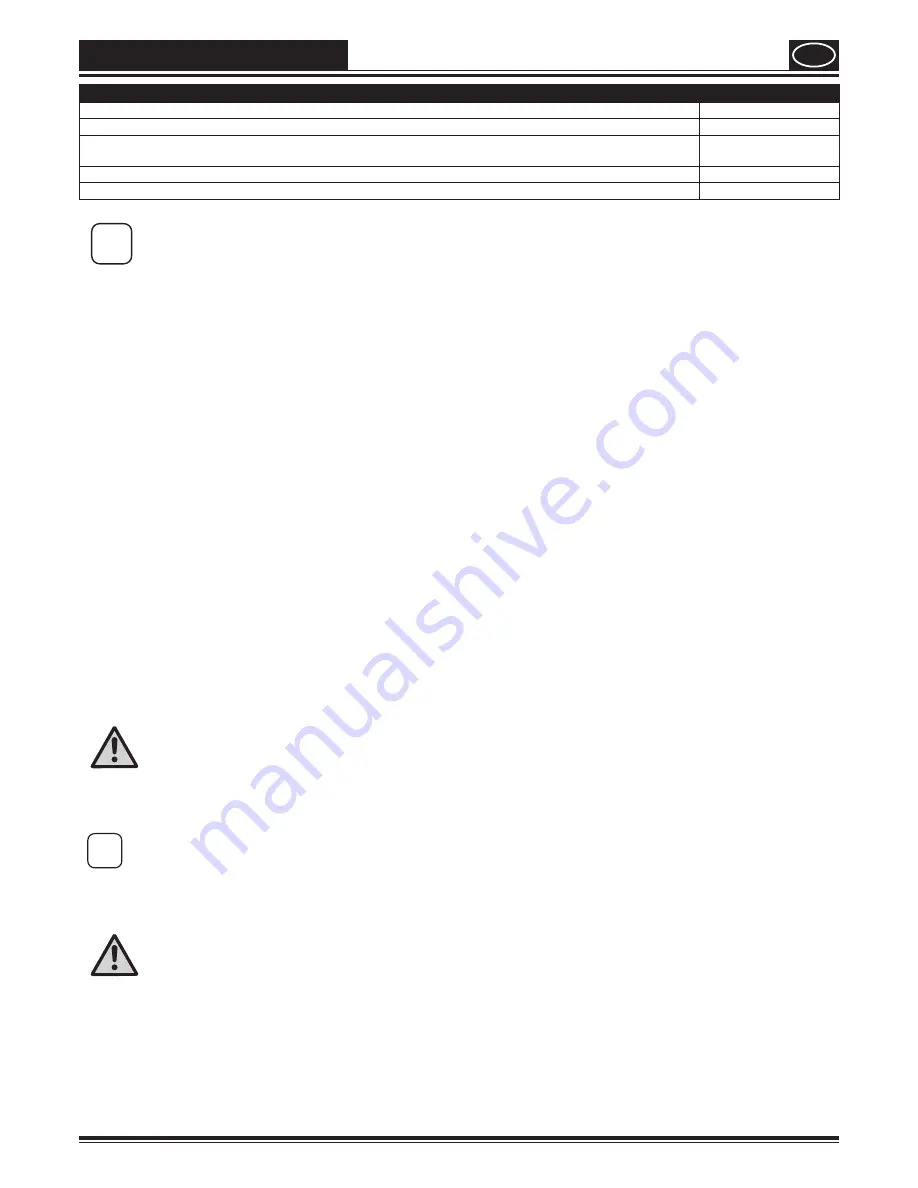
Thinning recommendation

Sprayed material

Glazes

undiluted

Wood preservatives containing solvents or based on water, mordants, oils, disinfection agents, plant 

protective agents

undiluted

Paints containing solvents and watersoluble paints, primers, vehicle coating paints, thick-film glazes

dilute by 5 - 10 % 

Interior wall paint (dispersions and latex paint)

dilute by 0-10 % 


i

The values in the table are reference values. 

Find out how much the paint needs to be thinned by testing it. Details on how to test the spray paint can be found 

in the section called "Spray Technique".

Assembly

1.   Place both doors / flaps in the storage compartment.

2.   Insert the handle as shown in the picture and secure it by pushing downwards. (Fig. 2)

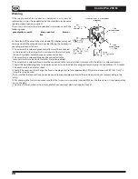
3.   Remove the protective covers on the hose and hose connection. (Fig. 3)

4.   Place the spray gun against the tapered end of the hose (Fig. 4, 1) and twist the gun onto the hose. Firmly tighten the thread 

using a wrench (13).

5.   Push the hose into the fixing (Fig. 4, 2) until it engages. 

6.   Twist the thread at the other end of the hose onto the hose connection.   

Using a wrench (16), hold the hose connection firmly and tighten the hose with another wrench (17). (Fig. 5)

7.   Slide the suction hose onto the inlet valve. Secure with the clamp. (Fig. 6)

8.   Press the return hose onto the return hose fitting. Secure with the clamp. (Fig. 7)

Control elements on the device (Fig. 8)

A

The pressure of the spray is set by the pressure regulator. 

The correct spray pressure depends on the paint being used. 

The device is switched off if the pressure regulator is in position 0.

B

The following settings can be made with the selector switch:
PRIME (Switch set vertically)

• 

For prefilling the system with paint

• 

For pressure relief

SPRAY (Switch set horizontally)

• 

For using the spray gun 

Spray Gun

Danger

Always lock the trigger off when attaching the spray nozzle or when the spray gun is not in use. 

• 

Fold the trigger lock downwards to lock the trigger (Fig. 9, A).

• 

Fold the trigger lock upwards to unlock the trigger (Fig. 9, B).

i

Another nozzle size may be used, depending on the material to be processed.


Information about all the available nozzles can be found in the section about "Accessories". 

Pressure Relief Procedure

Danger

Be sure to follow the Pressure Relief Procedure when shutting the unit off for any purpose.  

This procedure relieves the pressure from the spray hose and the gun.

1.   Secure the spray gun. (Fig. 9, A)

2.   Switch the device off (pressure regulator in position 0).   

Turn the switch into the PRIME position (vertical). (Fig. 10) 

3.   Release the spray gun. Hold the spray gun over an empty container and press the trigger to relieve the pressure.

4.   Secure the spray gun.

Summary of Contents for CONTROL PRO 250 M

Page 1: ...wagner group com D GB NL F I E P DK S UNIVERSAL SPRAYER CONTROL PRO 250 M ORIGINAL BETRIEBSANLEITUNG...

Page 2: ...Control Pro 250 M 2 12 14 3 4 7 6 5 9 11 15 13 1 10 8 wagner group com D GB NL F I E P DK S HIGH EFFICIENCY AIRLESS CONTROL PRO 100 BETRIEBSANLEITUNG a 1 2 1 2 1 2...

Page 3: ...Control Pro 250 M SPRAY PRIME A B A PRIME SPRAY B SPRAY PRIME SPRAY PRIME 0 OFF 1 2 1 2 A B...

Page 4: ...Control Pro 250 M 20 25 cm A B C 20 25cm 20 25 cm 20 25 cm D A B...

Page 5: ...Control Pro 250 M 1 2 3 4 1 2 3 4 5 HOUSEHOLD OIL 1 5 2 3 4 6 7 15 16 17 8 9 10 11 12 13 14...

Page 6: ...spray gun using the safety catch on the trigger 3 Ensure that the unit is properly earthed The connection must take place through a correctly earthed two pole and earth socket outlet 4 Check allowable...

Page 7: ...areas that contain flammable liquids gases or dusts Power tools generate sparks that can ignite the dust or vapors c Keep children and other persons away when using the power tool You can lose control...

Page 8: ...tch is defective A power tool that cannot be switched on or off is dangerous and has to be repaired c Remove the plug from the socket before carrying out tool settings changing accessories or putting...

Page 9: ...f interruption to work Recoil of spray gun Danger In case of high operating pressure pulling the trigger can effect a recoil force of up to 15 N If you are not prepared for this your hand can be thrus...

Page 10: ...between the unit and spray gun is to be maintained When working outdoors Vapors containing solvents may not be allowed to blow toward the unit Note the direction of the wind Set the unit up in such a...

Page 11: ...and auxiliary material Wrench 13 16 17 20 and or adjustable wrench 2 pcs and hex key 10 mm Hex key 2 5 mm Empty container A large piece of cardboard Covering material Preparation of the workplace Dan...

Page 12: ...lve Secure with the clamp Fig 6 8 Press the return hose onto the return hose fitting Secure with the clamp Fig 7 Control elements on the device Fig 8 A The pressure of the spray is set by the pressure...

Page 13: ...as shown in fig 17 B gradually increase the pressure or dilute more in 5 steps please note the maximum amount of thinner stipulated by manufacturer The key to obtaining a high quality result is even...

Page 14: ...er or suitable cleaning solution 5 Turn the switch to the SPRAY position and set maximum pressure 6 Hold the spray gun at the edge of an empty container Fig 21 Danger Ground gun with a metal container...

Page 15: ...laced Problems can be avoided by cleaning and servicing the device properly 1 Remove the high pressure hose from the base unit using a wrench 17 2 Loosen the screw hex key 2 5 mm on the outlet valve F...

Page 16: ...l strain Attention The vibration emission value can differ from the specified value when the electric tool is actually in use depending on how the electric tool is being used It is necessary to specif...

Page 17: ...ck The inlet valve is worn or damaged The PRIME SPRAY valve is plugged Try to prime the unit again Refill the bucket or immerse the suction tube in paint Clean the suction tube Tighten it securely Pre...

Page 18: ...e been carried out for products where the serial number has been removed or is illegible for products where the serial number has been removed or is illegible for products with slight deviations from...

Page 19: ...ed blue must be connected to the terminal which is marked with the letter N or coloured black The wire which is coloured brown must be connected to the terminal which is marked with the letter L or co...

Page 20: ...564 23 Bankeryd Sweden T 46 0 36 37 63 00 ROMIB S R L str Poligonului nr 5 7 100070 Ploiesti judet Prahova T 40 344801240 F 40 344801239 ROM ORKLA HOUSE CARE NORGE AS Nedre Sk yen vei 26 PO Box 423 S...

Reviews: