
23
Control Pro 350 Extra Skid
GB
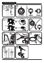
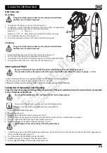
Pressure Relief Procedure
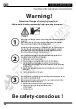
Danger
Be sure to follow the Pressure Relief Procedure when shutting the unit off for any purpose.
This procedure relieves the pressure from the spray hose and the gun. Watch the pressure gauge ––> 0 bar
1.
Secure the spray gun. (Fig. 9, A)
2. Switch the device off (pressure regulator in position 0).
Turn the switch into the PRIME position (vertical). (Fig. 10)
3. Release the spray gun. Hold the spray gun over an empty container and press the trigger to relieve the pressure.
4. Secure the spray gun.
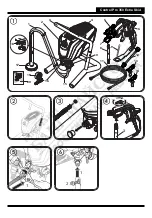
Start-up
Before connecting to the mains supply, be sure that the supply voltage is identical with the value given on the rating plate.
1. Attach the return pipe to the suction hose using the clamps.
2. Lower the suction hose into the paint container. (Fig. 11)
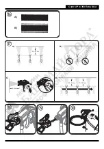
3. Press the red inlet valve pusher to ensure that the inlet valve is free. (Fig. 12)
4. Plug in the power cable.
5. Turn the switch into the PRIME position (vertical).
6. Switch the device ON by turning the pressure regulator slowly into position 2.
7. Switch the device off again (pressure regulator 0) as soon as the paint flows through the return pipe and into the paint container.
i
If no paint is sucked in, try to solve the problem with the steps described in the following chapter "Help with suction
problems".
8. Turn the switch to the SPRAY position (horizontal).
9. Hold the spray gun at the edge of an empty container. (Fig. 13)
10. Release the spray gun and hold the trigger until the material emerges evenly.
11. Let go of the trigger and secure the spray gun.
12. Place the nozzle holder on the spray gun (Fig. 14, A ) and rotate it into the final position (Fig. 14, B), in order to fix it.
13. Insert the nozzle with the tip facing forward. (Fig. 15)
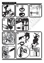
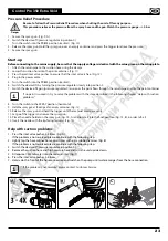
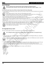
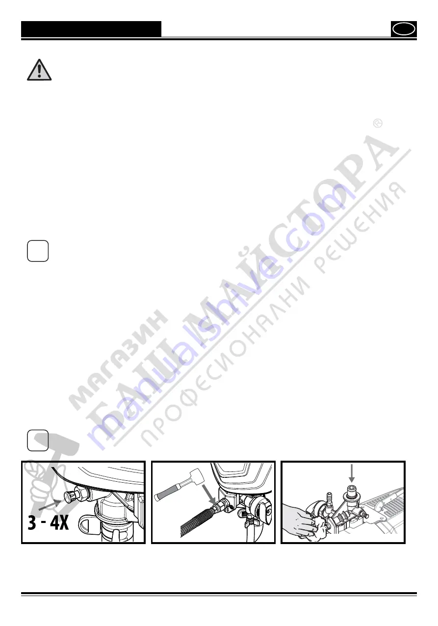
Help with suction problems
1. Press the inlet valve pusher 3-4 times. (Fig. A)
If the problem is not resolved, please continue with the following step.
2. Lightly tap the hose connection several times with e.g. a rubber hammer. (Fig. B)
If the problem is not resolved, please continue with the following step.
3. Switch the device off (pressure regulator in position 0).
4. Remove the suction hose and high pressure hose and turn the unit upside down.
5. Fill approx. 10 ml of water into the material inlet. (Fig. C)
6. Press the inlet valve pusher 3-4 times.
7. Hold a cloth in front of the hose connection and switch on the pump until water emerges from the hose connection.
i
If the problem is not resolved, please contact Customer Service
A
B
C


