background image

24

Control Pro 350 Extra Skid

GB

Spray Technique

Danger

Be sure to follow the Pressure Relief Procedure when shutting the unit off for any purpose.  

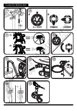
This procedure relieves the pressure from the spray hose and the gun. Watch the pressure gauge ––> 0 bar

Be sure that the paint hose is free of kinks and clear of objects with sharp cutting edges. 

• 

It is best to practise on cardboard or a similar surface first of all, in order to check the spray pattern and become accustomed to 

using the spray gun. 

i

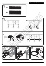
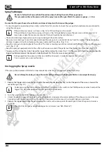
If the paint sprays evenly, as shown in fig. 16 A, all the setting must be correct. 

If the paint looks stripy after spraying, as shown in fig. 16 B, gradually increase the pressure, or dilute more in 5% 

steps (please note the maximum amount of thinner stipulated by manufacturer.) 

• 

The key to obtaining a high quality result is even coating of the entire surface. 

Keep your arm moving at a constant speed and keep the spray gun at a constant distance from the surface. The best spraying 

distance is approx. 20 to 25 cm between the spray nozzle and the surface.  (Fig. 17, A)

• 

Keep the spray gun at right angles to the surface. This means moving your entire arm back and forth rather than just flexing your 

wrist. (Fig. 17, B)

• 

Keep the spray gun perpendicular to the surface, otherwise one end of the pattern will be thicker than the other. (Fig. 17, C)

• 

Trigger gun after starting the stroke. Release the trigger before ending the stroke. (Fig. 17, D) The spray gun should be mo

ving when the 

trigger is pulled and released. Overlap each stroke by about 30%. This will ensure an even coating.


i

During operation the pump switches on and off continuously, in order to regulate the pressure. 

This is normal and is not a malfunction.

Unclogging the Spray nozzle

If the spray pattern becomes distorted or stops completely while the gun is triggered, follow these steps.

Danger


Do not attempt to unclog or clean the nozzle with your finger. High pressure fluid can cause injection injury.

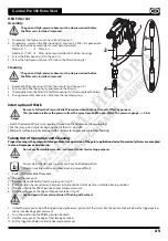
1.   Release the trigger and secure the gun. Rotate the reversible nozzle arrow 180º so that the point of the arrow is toward the 

rear of the gun. (

Fig. 18

). 

i

Under pressure, the nozzle may be very difficult to turn. Turn the switch to the PRIME position (vertical) and pull the 

trigger. This will relieve pressure and the tip will turn more easily.


2.  

Turn the switch to the SPRAY position (horizontal).

3.   Unlock the gun and squeeze the trigger, pointing the gun at a scrap piece of wood or cardboard. This allows pressure in the spray 

hose to blow out the obstruction. When the nozzle is clean, material will come out in a straight, high pressure stream.

4.  

Release the trigger and secure the gun.

 Reverse the nozzle so the arrow points forward again. Unlock the gun and resume 

spraying.

i


The HEA Filter Set keeps nozzle blockages to a minimum (see “HEA Filter Set”).

Summary of Contents for CONTROL PRO 350 EXTRA SKID

Page 1: ...wagner group com D GB NL F I E P DK S HIGH EFFICIENCY AIRLESS CONTROL PRO 350 EXTRA SKID ORIGINAL BETRIEBSANLEITUNG...

Page 2: ...Control Pro 350 Extra Skid 2 16 18 3 4 7 6 5 11 15 20 17 1 10 13 19 12 14 8 9 wagner group com D GB NL F I E P DK S HIGH EFFICIENCY AIRLESS CONTROL PRO 100 BETRIEBSANLEITUNG 1 2 1 2 1...

Page 3: ...Control Pro 350 Extra Skid SPRAY PRIME A PRIME SPRAY B SPRAY PRIME SPRAY PRIME 0 OFF 1 2 A B A B...

Page 4: ...Control Pro 350 Extra Skid 20 25 cm A B C 20 25cm 20 25 cm 20 25 cm D A B...

Page 5: ...Control Pro 350 Extra Skid 7 6 16 17 18 8 9 10 11 12 13 14 15 1 4 2 3 5 1 2 3 4 1 2 3 4 5 HOUSEHOLD OIL...

Page 6: ...Secure spray gun using the safety catch on the trigger 3 Ensure that the unit is properly earthed The connection must take place through a correctly earthed two pole and earth socket outlet 4 Check a...

Page 7: ...ous areas that contain flammable liquids gases or dusts Power tools generate sparks that can ignite the dust or vapors c Keep children and other persons away when using the power tool You can lose con...

Page 8: ...switch is defective A power tool that cannot be switched on or off is dangerous and has to be repaired c Remove the plug from the socket before carrying out tool settings changing accessories or putt...

Page 9: ...ase of interruption to work Recoil of spray gun Danger In case of high operating pressure pulling the trigger can effect a recoil force of up to 15 N If you are not prepared for this your hand can be...

Page 10: ...5 m between the unit and spray gun is to be maintained When working outdoors Vapors containing solvents may not be allowed to blow toward the unit Note the direction of the wind Set the unit up in su...

Page 11: ...cidic coating substances Flammable materials materials containing acetone or cellulose thinner i In order to ensure compatibility of the coating substance with the materials used to manufacture the de...

Page 12: ...gun against the tapered end of the hose Fig 4 1 and twist the gun onto the hose Firmly tighten the thread using a wrench 13 Danger To check whether or not the hose is pressurized the provided pressure...

Page 13: ...h the return pipe and into the paint container i If no paint is sucked in try to solve the problem with the steps described in the following chapter Help with suction problems 8 Turn the switch to the...

Page 14: ...icker than the other Fig 17 C Trigger gun after starting the stroke Release the trigger before ending the stroke Fig 17 D The spray gun should be moving when the trigger is pulled and released Overlap...

Page 15: ...position 0 and remove the power plug Put the spray gun in a plastic bag and seal so that it is air tight Wet paint surface in paint container with a little water to prevent a skin from forming Taking...

Page 16: ...the socket a Cleaning the inlet valve i If any problems occur when the paint is sucked up the intake valve needs to be cleaned or replaced Problems can be avoided by cleaning and servicing the device...

Page 17: ...17517 Nozzle 619 60 spray angle 0 019 inch nozzle diameter 0517619 Filter red nozzle 211 311 313 413 1 pack 34383 Filter red nozzle 211 311 313 413 10 pack 97022 Filter yellow nozzle 515 1 pack 43235...

Page 18: ...ressure No voltage is coming from the wall plug The extension cord is damaged or has too low a capacity Device overheated There is a problem with the motor Plug the sprayer in Perform pressure relief...

Page 19: ...llows The wire which is coloured green and yellow must be connected to the terminal in the plug which is marked with the letter E or by the earth symbol or coloured green or green and yellow The wire...

Page 20: ...e target properties which are negligible with regard to the value and usability of the device The unit is not conceived for use in shift work or for lending or leasing these uses are excluded from the...

Reviews: