background image

26

Control Pro 350 Extra Skid

GB

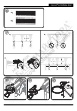
11.  Switch the device off and remove the power plug.

12.  Turn the switch into the PRIME position (vertical).

13.  Pull the trigger to relieve the pressure.

14.  Secure the spray gun.

15.  Separate the spray gun from the paint hose using wrenches (13).

i


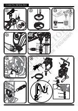
If the HEA filter set is being used, remove it and clean it in accordance with the information in the chapter entitled 

"HEA Filter Set".

16.  Remove the nozzle (1), plain washer (2) and the mounting (3) from the nozzle holder (4) and clean all parts thoroughly. 

(Fig.21) 

17.  Replace the mounting and the plain washer in the nozzle holder.  

Screw the nozzle holder onto the gun.

18.  Detach the suction hose from the basic unit.

19.  Disconnect the return line.

20.  Wipe off the exteriors of both hoses.

21.  Carefully remove the filter disc (1) from the suction filter. (Fig. 22) 

22.  Clean the filter disk thoroughly under running water.

23.  Remove the high pressure hose from the basic unit with a wrench (17).

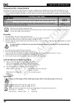
24.  Immerse the inlet valve in a container filled with conservation agent (e.g. household oil). (Fig. 23)

25.  Insert the power plug.

26.  Hold a cloth in front of the hose connection and switch the device on for approx. 5 seconds. (Fig. 24) 

This procedure preserves the pump.

Maintenance and repairs

Danger


Before carrying out any work on the device, relieve the pressure and unplug the power plug from the socket.

a) Cleaning the inlet valve

i

If any problems occur when the paint is sucked up, the intake valve needs to be cleaned or replaced. Problems can 

be avoided by cleaning and servicing the device properly.

1.  

Detach the suction hose from the basic unit.

2.  

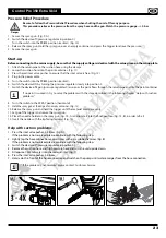
Remove the inlet valve (Fig. 25, 1) from the base unit using a wrench (20 or Allen wrench 10mm). 

3.   Remove the valve seat (Fig. 25, 2), ball (3) and O-ring (4) from the inlet valve. 

4.   Clean the inlet valve mount and all components thoroughly with a suitable cleaning solution or replace them if necessary.

5.   Lubricate the O-ring (Fig. 25, 5) on the inlet valve.

6.   Place the valve seat, ball and O-ring back in the inlet valve.

7.   Replace inlet valve assembly by screwing it into the sprayer.

b) Cleaning the outlet valve

i

If the spray pattern is poor, the outlet valve may need to be cleaned or replaced.  

Problems can be avoided by cleaning and servicing the device properly.

1.  

Remove the high-pressure hose from the base unit using a wrench (17).

2.   Loosen the screw (Allen wrench  2.5 mm) on the outlet valve (Fig. 26), but do not remove it.

3.   Remove the outlet valve (Fig. 27, 1) from the base unit using a wrench (16).

4.   Clean the outlet valve mount and the outlet valve thoroughly with a suitable cleaning solution or replace the outlet valve if 

necessary.

5.   Put the new or cleaned outlet valve back in.  

6.   Re-tighten the screw (Fig. 26).

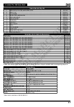
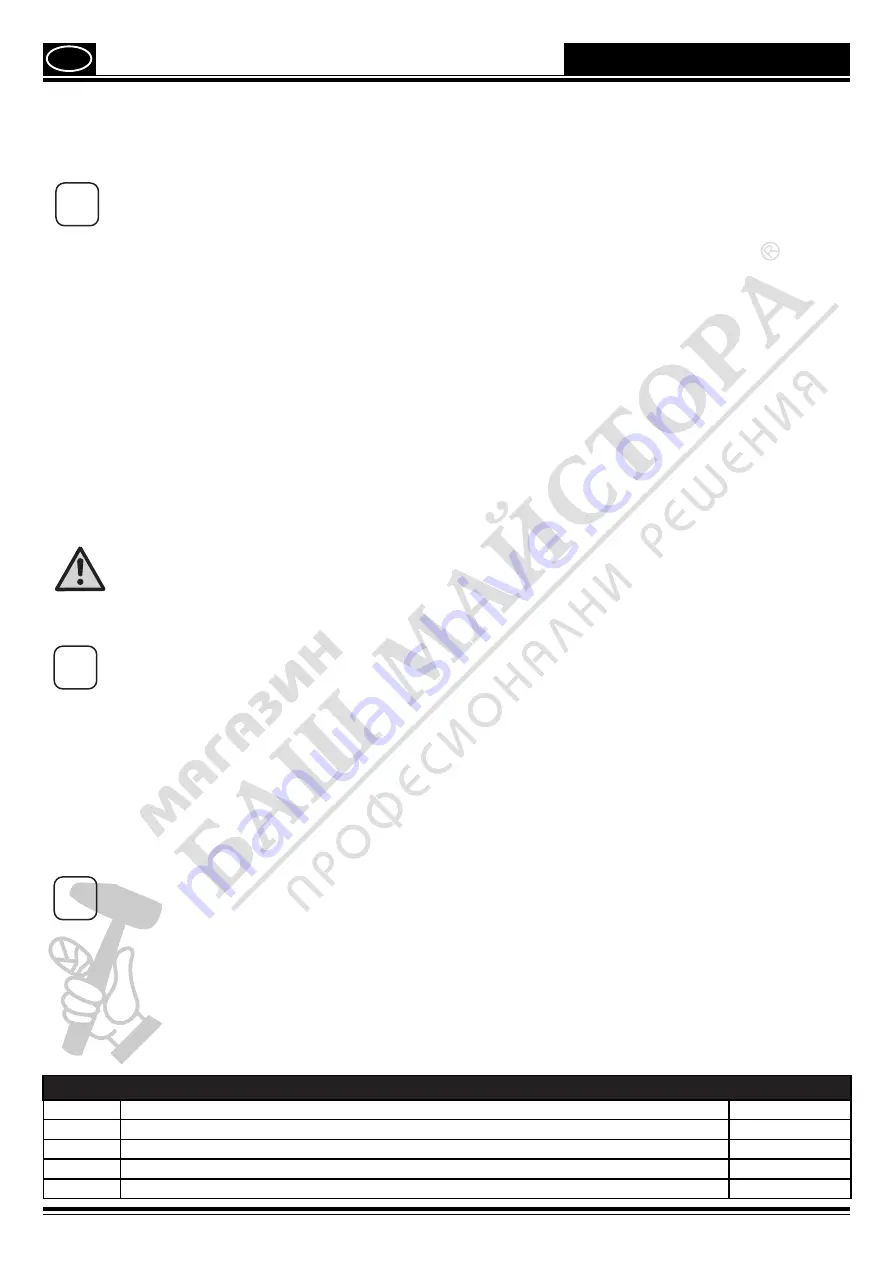
Spare Parts List (Fig. 28)

Pos.

Description

Order No.

1

Spray gun assembly (incl. nozzle holder)

0517101

2

Nozzle holder

0517200

3

Sealing set

0517900

4

High-pressure hose, 15 m 

0517802

Summary of Contents for CONTROL PRO 350 EXTRA SKID

Page 1: ...wagner group com D GB NL F I E P DK S HIGH EFFICIENCY AIRLESS CONTROL PRO 350 EXTRA SKID ORIGINAL BETRIEBSANLEITUNG...

Page 2: ...Control Pro 350 Extra Skid 2 16 18 3 4 7 6 5 11 15 20 17 1 10 13 19 12 14 8 9 wagner group com D GB NL F I E P DK S HIGH EFFICIENCY AIRLESS CONTROL PRO 100 BETRIEBSANLEITUNG 1 2 1 2 1...

Page 3: ...Control Pro 350 Extra Skid SPRAY PRIME A PRIME SPRAY B SPRAY PRIME SPRAY PRIME 0 OFF 1 2 A B A B...

Page 4: ...Control Pro 350 Extra Skid 20 25 cm A B C 20 25cm 20 25 cm 20 25 cm D A B...

Page 5: ...Control Pro 350 Extra Skid 7 6 16 17 18 8 9 10 11 12 13 14 15 1 4 2 3 5 1 2 3 4 1 2 3 4 5 HOUSEHOLD OIL...

Page 6: ...Secure spray gun using the safety catch on the trigger 3 Ensure that the unit is properly earthed The connection must take place through a correctly earthed two pole and earth socket outlet 4 Check a...

Page 7: ...ous areas that contain flammable liquids gases or dusts Power tools generate sparks that can ignite the dust or vapors c Keep children and other persons away when using the power tool You can lose con...

Page 8: ...switch is defective A power tool that cannot be switched on or off is dangerous and has to be repaired c Remove the plug from the socket before carrying out tool settings changing accessories or putt...

Page 9: ...ase of interruption to work Recoil of spray gun Danger In case of high operating pressure pulling the trigger can effect a recoil force of up to 15 N If you are not prepared for this your hand can be...

Page 10: ...5 m between the unit and spray gun is to be maintained When working outdoors Vapors containing solvents may not be allowed to blow toward the unit Note the direction of the wind Set the unit up in su...

Page 11: ...cidic coating substances Flammable materials materials containing acetone or cellulose thinner i In order to ensure compatibility of the coating substance with the materials used to manufacture the de...

Page 12: ...gun against the tapered end of the hose Fig 4 1 and twist the gun onto the hose Firmly tighten the thread using a wrench 13 Danger To check whether or not the hose is pressurized the provided pressure...

Page 13: ...h the return pipe and into the paint container i If no paint is sucked in try to solve the problem with the steps described in the following chapter Help with suction problems 8 Turn the switch to the...

Page 14: ...icker than the other Fig 17 C Trigger gun after starting the stroke Release the trigger before ending the stroke Fig 17 D The spray gun should be moving when the trigger is pulled and released Overlap...

Page 15: ...position 0 and remove the power plug Put the spray gun in a plastic bag and seal so that it is air tight Wet paint surface in paint container with a little water to prevent a skin from forming Taking...

Page 16: ...the socket a Cleaning the inlet valve i If any problems occur when the paint is sucked up the intake valve needs to be cleaned or replaced Problems can be avoided by cleaning and servicing the device...

Page 17: ...17517 Nozzle 619 60 spray angle 0 019 inch nozzle diameter 0517619 Filter red nozzle 211 311 313 413 1 pack 34383 Filter red nozzle 211 311 313 413 10 pack 97022 Filter yellow nozzle 515 1 pack 43235...

Page 18: ...ressure No voltage is coming from the wall plug The extension cord is damaged or has too low a capacity Device overheated There is a problem with the motor Plug the sprayer in Perform pressure relief...

Page 19: ...llows The wire which is coloured green and yellow must be connected to the terminal in the plug which is marked with the letter E or by the earth symbol or coloured green or green and yellow The wire...

Page 20: ...e target properties which are negligible with regard to the value and usability of the device The unit is not conceived for use in shift work or for lending or leasing these uses are excluded from the...

Reviews: