background image

18

FinishControl 3500

GB

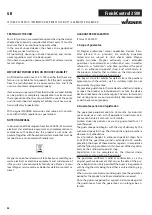
EXPLANATORY DIAGRAM (FIG. 1)

THE WAGNER CLICK&PAINT SYSTEM

With the Wagner Click&Paint System, the front part of the gun (spray attachment) can be replaced quickly and easily. 

This enables a rapid material change without cleaning, and ensures that the right tool is available for every material and applica-

tion.

The following spray attachments are available:

Spray attachment

Area of application

StandardSpray (yellow) 

Order No. 2321 879

Spray attachment with slit nozzle and 1000 ml stainless steel container. Processes all standard 

paints. 

FineSpray (brown) 

Order No. 2321 877

Spray attachment with round nozzle and 1000 ml stainless steel container. Ideal for low-viscosity 

paints and glazes.

WallSpray (white) 

Order No. 2321 880

Dispersion spray attachment with slit nozzle and 1400 ml plastic container. Designed for processing 

dispersions and latex paint.

3.1 

DISASSEMBLY OF THE SPRAY GUN

For assembly, insert the spray attachment into the FC 3500 so that the two arrows point at each other.  

Turn the FC 3500 90° in the arrow direction until it audibly engages. (Fig. 2)

To remove the spray attachment, push the catch (Fig. 2, A) beneath the trigger down and turn the spray attachment by 90°.

EXPLANATORY DIAGRAM/ CLICK&PAINT SYSTEM

POS. DESIGNATION

1

Nozzle

2

Air cap

3

Spray jet width adjusting lever (shaping air)

4

Spray jet level adjusting ring (vertical/horizontal)

5

Union nut

6

Spray attachment complete

7

Material volume regulation

8

Fixture for shoulder strap

9

Air filter cover lock

10

Air filter cover

11

Air volume control

12

Power cable

13

Click&Paint catch

14

Trigger (actuates turbine starting switch 

 material is 

conveyed)

POS. DESIGNATION

15

Container

16

Suction tube

17

Container seal

18

Valve

19

Ventilating hose

20

Cleaning brush

21

Fine feed tube filter (red) 

Coarse feed tube filter (white)

22

Funnel (3 pcs.)

23

Replacement air filter (3 pcs.)

24

Carrying strap (for device and transport case)

25

Transport case

26

Velcro to secure the power cable 

Summary of Contents for FC3500

Page 1: ...FinishControl 3500 2342387 02 2014...

Page 2: ...FinishControl 3500 1 2 A 3 A B 1 21 2 3 4 5 7 6 11 16 17 20 13 15 1 22 8 9 10 12 14 19 26 18 25 24 22 3 1 7 1 2...

Page 3: ...FinishControl 3500 1 1 1 A B 3 20 cm 1 2 1 2 1 7 1 7 2 7 3 7 4 8 8 9 12...

Page 4: ...FinishControl 3500 1 2 3 4 5 1 2 12 12 12 12 1 12 1 12 1 12 1 12 1 12 1 13 1 13 1...

Page 5: ...FinishControl 3500 3 2 1 14 1 2 3 5 6 7 8 9 10 11 12 13 15 4 2 1 3 4 5 6 7 8 13 2 11 11 15 2 15 3...

Page 6: ..._______ 21 12 TAKING OUT OF OPERATION AND CLEANING ___ 21 12 1 Assembly____________________________________ 22 13 MAINTENANCE______________________________ 22 13 1 Air filter__________________________...

Page 7: ...ry c Avoid accidental starting up Ensure that the switch is in the OFF position before inserting the plug into the socket Accidents can occur if you carry the power tool while your finger is on the sw...

Page 8: ...on working with and cleaning the equipment Protective clothing gloves and if necessary protective skin cream is required to protect the skin SAFETY REGULATIONS 4 Warning When working with the paint sp...

Page 9: ...SASSEMBLY OF THE SPRAY GUN For assembly insert the spray attachment into the FC 3500 so that the two arrows point at each other Turn the FC 3500 90 in the arrow direction until it audibly engages Fig...

Page 10: ...atomised by the rest of the atomisation air All settings necessary for operation e g material volume can be conveniently made directly on the gun Field of application The FC 3500 is designed for smal...

Page 11: ...oned correctly the container contents can be sprayed without almost any residue When working on lying objects Turn the feed tube forwards Fig 7 A Spraying work when working on overhead objects Turn th...

Page 12: ...ies inside the case as shown in fig 25 and secure with elastic straps Press the right and left inside of the case lid out wards in order to open up the transport case com pletely PUSH 12 TAKING OUT OF...

Page 13: ...ted extent Do not immerse in solvent only wipe 10 Remove the adjusting ring fig 13 1 carefully from the union nut 2 Unscrew union nut 2 remove air cap 3 nozzle 4 and nozzle seal 5 Thoroughly clean all...

Page 14: ...o mains voltage Check No coating material emerges from the nozzle Nozzle clogged Material volume setting too low Paint container seal damaged No pressure build up in container Container empty Ventilat...

Page 15: ...ssive paint mist overspray Distance to the object too large Too much coating material applied Amount of air too high Coating substance over diluted Incorrect spray attachment Incorrect spraying techni...

Page 16: ...FIG 27 POS ORDER NO DESIGNATION 1 2321 879 StandardSpray spray attachment yellow with 1000 ml container 2 2314 594 Spray jet width adjusting lever 3 2314 591 Spray jet adjustment ring 4 2332 577 Unio...

Page 17: ...gner quality assurance Wagner exclusively issues extended guarantees to commercial or professional users hereafter referred to as customer who have purchased the prod uct in an authorised specialist s...

Page 18: ...than is intended abnormal ambient conditions unsuitable coating materials unsuitable operating conditions operation with the incorrect mains voltage supply frequency over operation or defective servi...

Page 19: ...ntes suivantes conforme alle segenti disposizioni pertinenti 2006 42 EG 2004 108 EG 2011 65 EG 2002 96 EG 2006 42 EC 2004 108 EC 2011 65 EC 2002 96 EC 2006 42 CE 2004 108 CE 2011 65 CE 2002 96 CE 2006...

Reviews: