24
FineCoat Split-Gun
GB
Maintenance
9.5
Replacing the check valve retainer, valve seal
and air tubes
The check valve is a one-way valve designed to allow air into the
cup, pressurizing the cup’s contents. Because it is a one-way valve, it
prevents paint from seeping up the air tube into the air passages of
the gun. It also eliminates any delay in material flow when the gun is
triggered by maintaining pressure in the cup.
The check valve rotates open easily for cleaning. It contains a valve
seal that can be removed and cleaned with soap and water for
waterborne materials or a compatible solvent for other materials. To
replace the valve seal, and/or the air tubes:
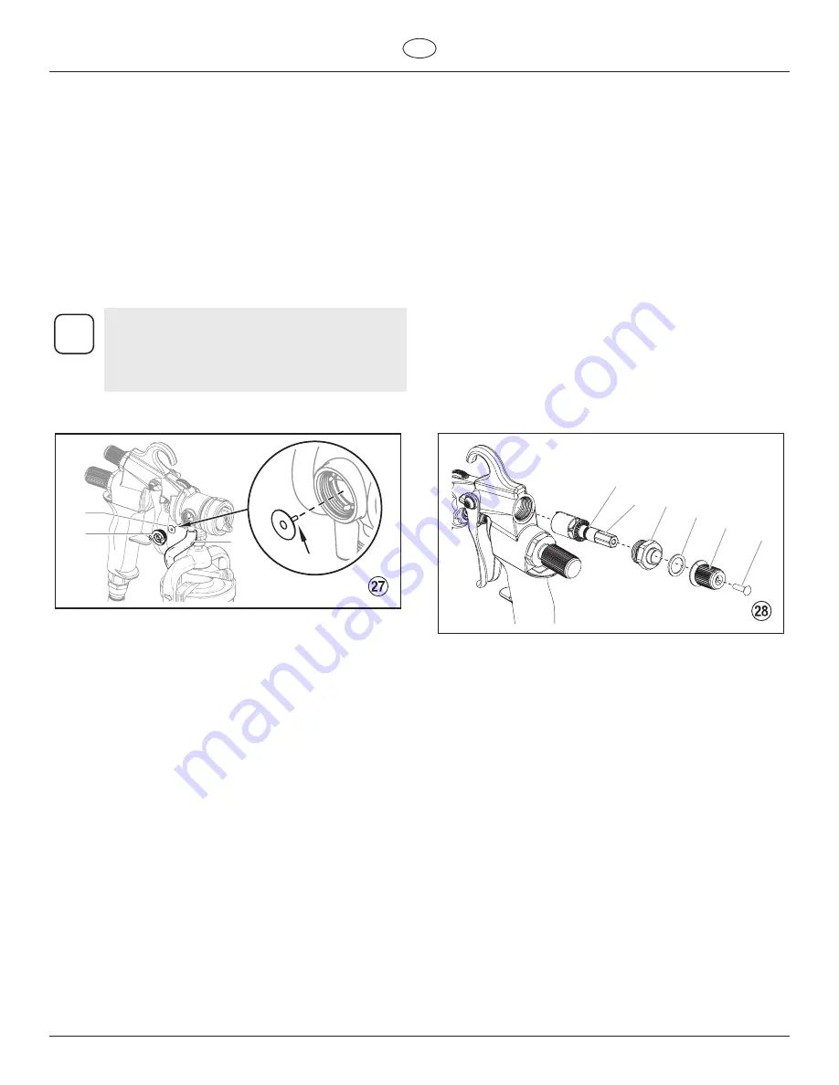
1. Unscrew the check valve retainer / o-ring (Fig. 27, item 1) by
turning it counterclockwise.
2. Pull the valve seal (2) out of the gun head. Clean or replace
the valve seal.
i
The check valve area inside the gun head should
also be cleaned of any accumulated spray material.
DO NOT use anything metal or abrasive to clean the
check valve area as it will scratch the metal surface,
and the valve seal will not seal properly.
3. Reinstall the valve seal (2). Insert the stem of the valve seal
into the hole of the gun head.
1
3
2
2
4. Screw the new or cleaned check valve retainer / O-ring (1)
back into the gun head by turning it clockwise.
5. To replace the air tube (3), pull it from the nipples on both the
gun head and the cup assembly. Replace with a new tube.
9.6
Replacing the air flow valve O-ring
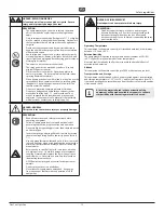
1. Using a wrench, loosen the air flow valve nut (Fig. 28, item 1)
and remove the air flow adjustment knob assembly.
2. Using a screwdriver, remove the adjustment knob screw (2).
Separate the adjusment knob (3) from the air flow valve nut
(1). Be careful not to lose the washer (4).
3. Separate the air flow valve (5) from the air flow valve nut (1).
The air flow valve O-ring (6) is located on the air flow valve (5).
4. Remove the air flow valve O-ring (6) from the air flow valve (5).
5. Lubricate the new O-ring with a small amount of petroleum
jelly, and replace into the gun body.
6. Reassemble the air flow adjustment knob assembly:
a. Insert the air flow valve (Fig. 28, item 5) into the rear of the
spray gun.
b. Place the air flow valve nut (1) over the air flow valve and
thread it into the rear of the gun. Tigthen with a wrench.
c. Turn the air flow valve slightly counterclockwise until it does
not turn any further.
d. Install the wave washer (4).
e. Place the adjustment knob (3) over the air flow valve. The
mark on the knob should be in the 9:00 o’clock position (all
the way to the left).
f. Secure the adjustment knob with the screw (2). Tighten with
a screwdriver.
1
5
6
2
3
4


