20
FinishControl 4000 18V
EN
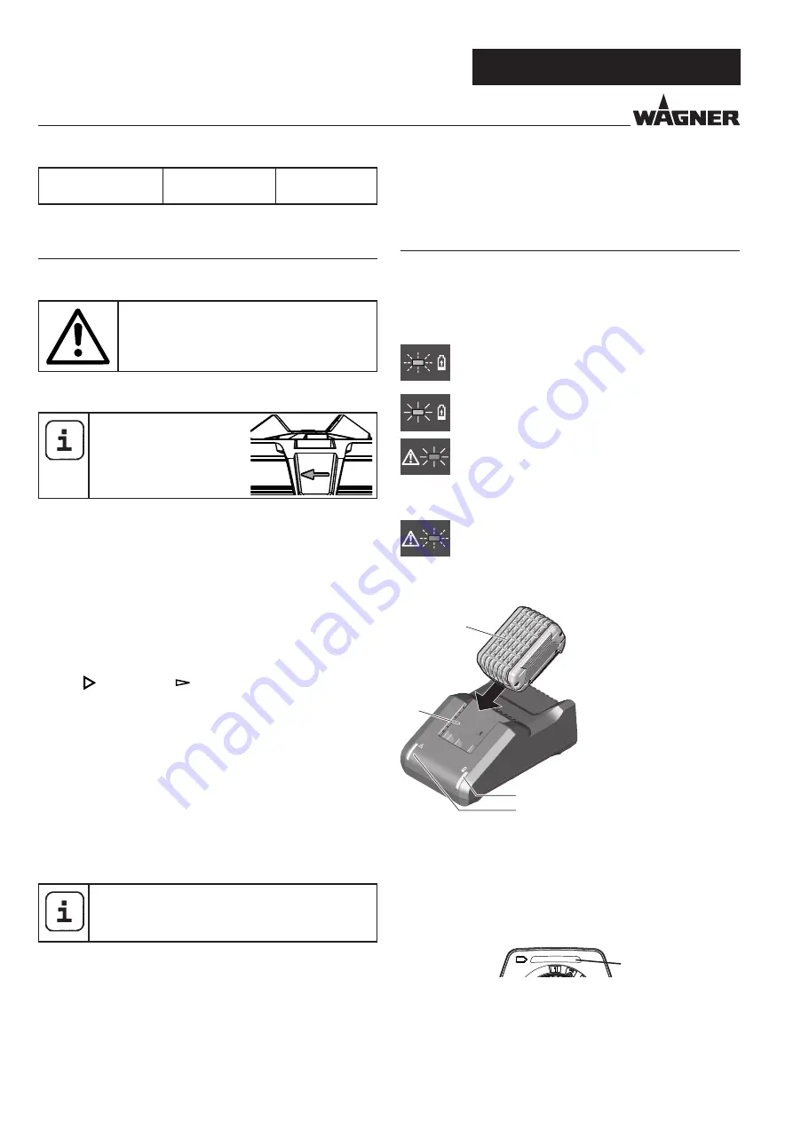
SETTING THE SPRAY GUN /CHARGING
Anti-rust paints, spe-
cial-effect paints
observe manufac-
turer’s instructions
7
SETTING THE SPRAY GUN
7.1
SETTING THE REQUIRED SPRAY PATTERN
Attention:
Never pull trigger while adjusting the air
cap settings.
2-3 different spray jet shapes can be set by turning the air cap
(fig. 3, 1)
Only turn the air cap in
the direction of the arrow,
since otherwise the union
nut can come loose.
A horizontal flat jet
for vertical surfaces
B
vertical flat jet
for horizontal surfaces
C* circular jet
for corners, edges and
hard-to-reach surfaces
* FineSpray spray attachment only
The controller (Fig. 4, 1) also allows the user to switch between
a wide ( ) and narrow ( ) spray jet.
7.2
SETTING THE AMOUNT OF MATERIAL (FIG. 5)
The material volume can be adjusted incrementally from 1
(minimum) to 12 (maximum) by turning the material volume
control (Fig. 5, 1).
7.3
SETTING THE AMOUNT OF AIR (FIG. 6)
Turn the air volume control (Fig, 6, 1) clockwise to increase the
air volume or anti-clockwise to reduce the air volume (note
arrow on body of gun).
The correct setting of air and material volume is
crucial for atomisation and paint mist formation.
7.4
ALIGN THE FEED TUBE
If the feed tube is positioned correctly, the container
contents can be sprayed without almost any residue.
When working on lying objects:
Turn the feed tube forwards. (Fig. 7 A)
Spraying work when working on overhead objects:
Turn the feed tube rearwards. (Fig. 7 B)
8
CHARGING
Before connecting to the mains, make sure that the mains
voltage corresponds to the specification on the charger‘s rating
plate.
Explanation of the indicator lights
When you insert the battery (1) into the charger (2)
the green indicator light (4) will begin to “BLINK”.
This indicates that the battery is charging.
A continuous green indicator light (4) indicates
that the battery is fully charged.
A steady red indicator light (3) means that the
battery is outside the proper temperature ranges
(between 0°C and 35°C). As soon as it falls within the
correct temperature range, the charging process
will automatically begin.
If the red indicator light (3) is “BLINKING”,
the contacts on the charger or battery are
contaminated, the battery is defective, or the
battery is not compatible with the charger. Clean
the contacts or replace the battery.
4
3
2
1
Plug charger cord into a standard power outlet (the charger’s
green indicator light (4) will switch ON).
1. Once the battery is fully charged, remove the battery
from the charger.
2. Unplug the mains plug of the charger from the socket.
Battery indicator
13
Green
Orange
Flashing orange
(handle vibrates)
=
=
=
Sufficient battery charge
Only minor work still possible
Battery must be charged
Summary of Contents for FINISH CONTROL 4000 18V
Page 2: ...FinishControl 4000 18V 1 2 3 A A C B 1 c 3 2 12 13 1 14 10 5 4 15 19 7 6 9 16 17 18 11 8 20...
Page 3: ...FinishControl 4000 18V A B 1 1 i 3 10 cm 1 2 j h 1 2 1...
Page 4: ...FinishControl 4000 18V o m q k p 1 l 1 3 2 2 6 1 5 3 n 2 r 1...
Page 5: ...FinishControl 4000 18V 3 2 1 1 2 4 6 7 8 9 10 5 s 3 3 4 2 1 5 7 t 6...
Page 131: ...125 FinishControl 4000 18V RU 1 1 a b c 2 a b c d e f 3 a b c d e f...
Page 132: ...126 FinishControl 4000 18V RU g h 4 a b c d e f g h 5 a b c d e f 130 C g...
Page 133: ...127 FinishControl 4000 18V RU 6 a b 1 2 3 4 5 6 7 1 4 14 2 8 9 10 11...
Page 140: ...134 FinishControl 4000 18V RU 14 14 1 1 2 18 1 3 18 2 14 2 1 19 1 2 3 2 3 4...
Page 141: ...135 FinishControl 4000 18V RU 15 10 14 2 13 1 2434518 14 1 16...
Page 145: ...139 FinishControl 4000 18V RU 4 Wagner 5 18 88677...
Page 146: ...140 FinishControl 4000 18V RU...
Page 147: ...141 FinishControl 4000 18V RU...


