22
FinishControl 4000 18V
EN
14.2
AIR RELIEF VALVE
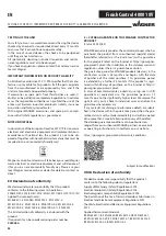
If paint has entered the ventilation hose, proceed
as follows:
1. Pull the ventilating hose (Fig. 19, 1) at the top from the
gun body. Screw off the valve cover (2). Remove the
diaphragm (3). Clean all the parts carefully.
CAUTION! The ventilation hose and
diaphragm are only solvent-resistant to a
limited extent. Do not immerse in solvent,
only wipe.
2. Place the diaphragm in the valve cover with the pin facing
forward (Also see the marking on the gun body).
3. Turn the body of the gun upside down and screw on the
valve cover from underneath.
4. Place the ventilating hose on the valve cover and on the
nipple at the gun body.
CAUTION! Never clean seals, diaphragm
and nozzle or air holes of the spray gun
with metal objects. The ventilation hose
and diaphragm are only solvent-resistant
to a limited extent. Do not immerse in
solvent, only wipe.
7. Move the air cap (Fig. 12, 1) to the vertical position for easier
removal and lift it off.
8. Unscrew the union nut (fig. 12, 2).
9. Clean the air cap (fig. 13, 1) and nozzle (3) with a brush and
solvent or water.
Take special care when cleaning the interstices on
the needle (Fig. 13, 5)
10. Clean the outside of the spray gun and container with a
cloth soaked in solvent or water. Use the all-purpose brush
for the thread (Fig. 13, 6).
11. Assemble the parts again (see “Assembly”).
13.1 ASSEMBLY
ATTENTION! Follow the steps described
below exactly for assembly. Otherwise
the spray attachment may be damaged.
1.
Push nozzle seal onto the needle so that the groove (slot)
points away from the spray attachment. (Fig. 14)
2.
Screw the union nut (Fig. 15, 2) onto the gun and tighten
it.
3.
Engage the air cap (Fig. 16, 1) with the union nut. Check if
the air cap has properly locked into place on both sides.
4. Place the container seal from below on the feed tube and
slide it over the collar, while turning the container seal
slightly.
5. Screw the feed tube with the container seal into the body
of the gun.
In order to mount the gun more easily apply
lubricating grease (enclosed) liberally to the O-ring
at the spray attachment (Fig. 17).
14
MAINTENANCE
14.1
AIR FILTER
Attention! Never operate the device with
the air filter soiled or missing, as dirt could
be sucked up and affect the operation of
the device. The air filter indicator lights up
red if the air filter needs to be changed.
1. Remove battery.
2. Open the cover on the air filter compartment (Fig. 18).
3. Depending on the degree of soiling, clean (blow out) the
air filter (Fig. 18, 2) or replace it.
MAINTENANCE
Summary of Contents for FINISH CONTROL 4000 18V
Page 2: ...FinishControl 4000 18V 1 2 3 A A C B 1 c 3 2 12 13 1 14 10 5 4 15 19 7 6 9 16 17 18 11 8 20...
Page 3: ...FinishControl 4000 18V A B 1 1 i 3 10 cm 1 2 j h 1 2 1...
Page 4: ...FinishControl 4000 18V o m q k p 1 l 1 3 2 2 6 1 5 3 n 2 r 1...
Page 5: ...FinishControl 4000 18V 3 2 1 1 2 4 6 7 8 9 10 5 s 3 3 4 2 1 5 7 t 6...
Page 131: ...125 FinishControl 4000 18V RU 1 1 a b c 2 a b c d e f 3 a b c d e f...
Page 132: ...126 FinishControl 4000 18V RU g h 4 a b c d e f g h 5 a b c d e f 130 C g...
Page 133: ...127 FinishControl 4000 18V RU 6 a b 1 2 3 4 5 6 7 1 4 14 2 8 9 10 11...
Page 140: ...134 FinishControl 4000 18V RU 14 14 1 1 2 18 1 3 18 2 14 2 1 19 1 2 3 2 3 4...
Page 141: ...135 FinishControl 4000 18V RU 15 10 14 2 13 1 2434518 14 1 16...
Page 145: ...139 FinishControl 4000 18V RU 4 Wagner 5 18 88677...
Page 146: ...140 FinishControl 4000 18V RU...
Page 147: ...141 FinishControl 4000 18V RU...


