background image

9

FinishControl 5500


EN

13.2 

AIR RELIEF VALVE

If paint has entered the ventilation hose, proceed 

as follows:

1.   Pull the ventilating hose (Fig. 20, 1) at the top from the 

gun body. Screw off the valve cover (2). Remove the 

diaphragm (3). Clean all the parts carefully.

CAUTION! The ventilation hose and 

diaphragm are only solvent-resistant to a 

limited extent. Do not immerse in solvent, 

only wipe.

2.   Place the diaphragm in the valve cover with the pin facing 

forward (Also see the marking on the gun body).

3.   Turn the body of the gun upside down and screw on the 

valve cover from underneath. 

4.   Place the ventilating hose on the valve cover and on the 

nipple at the gun body.

MAINTENANCE

Warning

If the supply cord of this appliance is damaged, it must only 

be replaced by a repair shop appointed by the manufacturer, 

because special purpose tools are required.

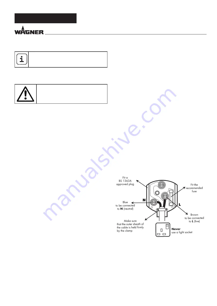
Warning: 

Do not connect the blue or brown wire to the earth 

terminal of the plug! The wires in this mains lead are coloured 

in accordance with the following code:

blue

 = neutral

 brown

 = live

As the colours of the wires in the mains lead of this appliance 

may not correspond with the coloured markings identifiying 

the terminals in your plug, proceed as follows:

Should the moulded plug have to be replaced, never re-use 

the defective plug or attempt to plug it into a different 13 A 

socket. This could result in an electric shock.

 Should it be necessary to exchange the fuse in the plug only 

use fuses approved by ASTA in accordance with BS 1362. 5 Amp 

fuses may be used.

 To ensure that the fuse and fuse carrier are correctly mounted 

please observe the provided markings or colour coding in the 

plug.

After changing the fuse, always make sure that the fuse carrier 

is correctly inserted. Without the fuse carrier, it is not permissible 

to use the plug.

 The correct fuses and fuse carriers are available from your 

local electrical supplies stockist.

Summary of Contents for FinishControl 5500

Page 1: ...FINISH CONTROL 5500 OPERATING MANUAL wagner group com EN...

Page 2: ...FinishControl 5500 1 1 2 3 A A B 1 c 24 3 2 11 12 1 13 9 5 4 14 23 18 25 7 6 8 15 16 17 19 20 21 22 10...

Page 3: ...FinishControl 5500 A B 2 1 1 1 1 3 10 cm 1 2 1 2...

Page 4: ...FinishControl 5500 r 1 q 1 s 1 3 2 2 6 1 5 3...

Page 5: ...FinishControl 5500 3 2 1 2 1 4 5 6 1 2 4 7 8 9 10 5 t 1 3 6 3...

Page 6: ...IN WORK_____________________________ 8 11 TRANSPORTATION____________________________ 8 12 TAKING OUT OF OPERATION AND CLEANING ____ 8 12 1 Assembly______________________________________8 13 MAINTENANC...

Page 7: ...FF position before inserting the plug into the socket Accidents can occur if you carry the power tool whileyourfingerisontheswitchorifyouconnectthepower tool to the power supply which it is on d Remov...

Page 8: ...ctive clothing gloves and if necessary protective skin cream is required to protect the skin 4 Warning When working with the paint spraying system both indoors and outdoors care should be taken that n...

Page 9: ...Paint System the front part of the gun spray attachment can be replaced quickly and easily This enables a rapid material change without cleaning and ensures that the right tool is available for every...

Page 10: ...terial volume can be conveniently made directly on the gun 6 COATING MATERIAL 6 1 COATING MATERIALS SUITABLE FOR USE Solvent based and water soluble lacquer paints Mordants glazes impregnations oils c...

Page 11: ...e rearwards Fig 7 B 8 STARTING OPERATION Before connecting to the mains supply make sure that the mains voltage corresponds to the operating voltage on the rating plate The unit must be connected with...

Page 12: ...se in solvent only wipe 7 Move the air cap Fig 13 1 to the vertical position for easier removal and lift it off 8 Unscrew the union nut fig 13 2 9 Clean the air cap fig 14 1 and nozzle 3 with a brush...

Page 13: ...quired Warning Do not connect the blue or brown wire to the earth terminal of the plug The wires in this mains lead are coloured in accordance with the following code blue neutral brown live As the co...

Page 14: ...ume too large Nozzle contaminated Viscosity of coating material too high Too little pressure build up in container Air filter heavily soiled Amount of air too low Air hose damaged Air cap assembled in...

Page 15: ...tins maximum dimensions 112 mm h 132 mm 15 2 SPARE PARTS FINISHCONTROL 5500 FIG 21 POS ORDER NO DESIGNATION 1 2434503 Filter cover set 2 2434505 Air filter 4 pcs 3 2434506 Storage compartment cover 4...

Page 16: ...ion of conformity is enclosed with the product If required it can be re ordered using order number 2434454 3 2 YEAR GUARANTEE ON THIS WAGNER CONTRACTOR PRODUCT Status 03 03 2022 WAGNER exclusively pro...

Page 17: ...13 FinishControl 5500 EN...

Page 18: ...14 FinishControl 5500 EN...

Page 19: ...15 FinishControl 5500 EN...

Page 20: ...22 9450 Altst tten Schweiz Tel 41 71 7 57 22 11 Telefax 41 71 7 57 22 22 wagner wagner group ch F Euromair Antony S A V Ile de France 12 14 av F Sommer 92160 Antony Tel 01 55 59 92 42 Telefax 33 0 1...

Reviews: