


2
EN
IMPORTANT SAFETY INFORMATION
TABLE OF CONTENTS
IMPORTANT SAFETY INFORMATION ........................................... 2-3
CONTROLS AND FUNCTIONS ............................................................. 4
OVERVIEW .................................................................................................. 5
MATERIAL PREPARATION .................................................................... 6
ASSEMBLY .................................................................................................. 7
POWER AND MATERIAL CONTROLS ................................................ 8
SPRAY PATTERN ADJUSTMENT ......................................................... 9
PROPER SPRAYING TECHNIQUE ............................................... 10-11
CLEANUP ............................................................................................ 12-13
MAINTENANCE .......................................................................................14
TROUBLESHOOTING ............................................................................15
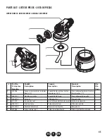
PARTS LIST......................................................................................... 44-46
LIMITED WARRANTY ............................................................................47
EXPLANATION OF SYMBOLS
Read all safety information before operating the equipment.
Save these instructions.
To reduce the risks of fire or explosion, electrical shock and the
injury to persons, read and understand all instructions included
in this manual. Be familiar with the controls and proper usage
of the equipment.
This symbol indicates a potential hazard
that may cause serious injury or loss of life.
Important safety information will follow.
Attention
This symbol indicates a potential hazard
to you or to the equipment. Important
information that tells how to prevent
damage to the equipment or how to avoid
causes of minor injuries will follow.
Danger of fire from solvent and paint fumes
Danger of explosion from solvent, paint
fumes and incompatible materials
Electric shock hazard
i
Notes give important information which
should be given special attention.
GROUNDING INSTRUCTIONS
This product must be grounded. In the event of an electrical
short circuit, grounding reduces the risk of electric shock by
providing an escape wire for the electric current. This product
is equipped with a cord having a grounding wire with an
appropriate grounding plug. The plug must be plugged into
an outlet that is properly installed and grounded in accordance
with all local codes and ordinances.
WARNING - Improper installation of the
grounding plug can result in a risk of electric
shock.
If repair or replacement of the cord or plug is necessary, do not
connect the green grounding wire to either flat blade terminal.
The wire with insulation having a green outer surface with
or without yellow stripes is the grounding wire and must be
connected to the grounding pin.
Check with a qualified electrician or serviceman if the grounding
instructions are not completely understood, or if you are in
doubt as to whether the product is properly grounded. Do not
modify the plug provided. If the plug will not fit the outlet,
have the proper outlet installed by a qualified electrician.
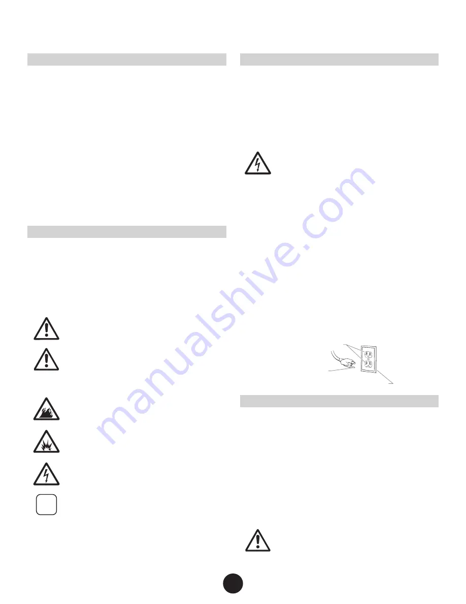
This product is for use on a nominal 120 volt circuit and has a
grounding plug that looks like the plug illustrated below. Make
sure that the product is connected to an outlet having the same
configuration as the plug. No adapter should be used with this
product.
Grounded Outlet
Grounding Pin
Cover for grounded outlet box
IMPORTANT ELECTRICAL INFORMATION
Use only a 3-wire extension cord that has a 3-blade grounding
plug and a 3-slot receptacle that will accept the plug on the
product. Make sure your extension cord is in good condition.
When using an extension cord, be sure to use one heavy enough
to carry the current your product will draw. An undersized cord
will cause a drop in line voltage resulting in loss of power and
overheating. A 14 gauge or 12 gauge cord is recommended. If
an extension cord is to be used outdoors, it must be marked with
the suffix W-A after the cord type designation. For example, a
designation of SJTW-A would indicate that the cord would be
appropriate for outdoor use.
Attention
Household use only. Intended for indoor/
outdoor use ONLY with materials having
flashpoint above 100ºF (38ºC).


