background image

English

2


© Wagner Spray Tech - All Rights Reserved

Important Safety Information

Read all safety information before 

operating the equipment.  Save these 

instructions.

Indicates a hazardous situation which, 

if not avoided, could result in death or 

serious injury.
To reduce the risks of fire or explosion, 

electrical shock and the injury to 

persons, read and understand all 

instructions included in this manual. Be 

familiar with the controls and proper 

usage of the equipment.

Grounding Instructions

This product must be grounded. In the event of an 

electrical short circuit, grounding reduces the risk 

of electric shock by providing an escape wire for 

the electric current. This product is equipped with a 

cord having a grounding wire with an appropriate 

grounding plug. The plug must be plugged into an 

outlet that is properly installed and grounded in 

accordance with all local codes and ordinances.

WaRnInG - Improper installation of 

the grounding plug can result in a risk 

of electric shock.

If repair or replacement of the cord or plug is 

necessary, do not connect the green grounding wire 

to either flat blade terminal. The wire with insulation 

having a green outer surface with or without yellow 

stripes is the grounding wire and must be connected 

to the grounding pin.
Check with a qualified electrician or serviceman 

if the grounding instructions are not completely 

understood, or if you are in doubt as to whether the 

product is properly grounded. Do not modify the 

plug provided.  If the plug will not fit the outlet, have 

the proper outlet installed by a qualified electrician.
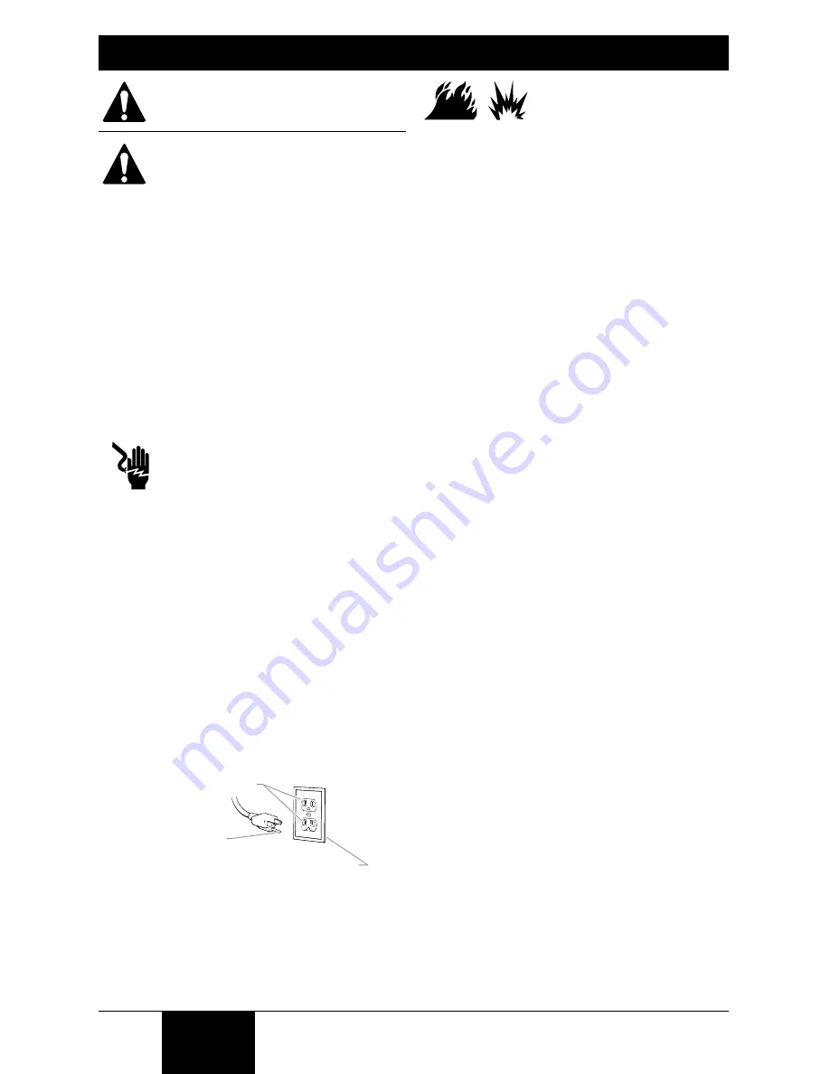
This product is for use on a nominal 120 volt 

circuit and has a grounding plug that looks like 

the plug illustrated below. Make sure that the 

product is connected to an outlet having the same 

configuration as the plug. No adapter should be 

used with this product.

Grounded Outlet

Grounding Pin 

Cover for grounded outlet box 

WaRnInG - To reduce the risk 

of fire or explosion:

  1.  Do not spray flammable or combustible 

materials near an open flame, pilot lights 

or sources of ignition such as hot objects, 

cigarettes, motors, electrical equipment and 

electrical appliances.  Avoid creating sparks 

from connecting and disconnecting power 

cords.

  2.  For use with only water-based or mineral 

spirit-type materials with a minimum flash point 

of 38ºC (100º F) — Do not spray or clean with 

liquids having a flash point of less than 38ºC 

(100º F).  Flash point is the temperature at which 

a fluid can produce enough vapor to ignite.

  3.  Verify that all containers and collection systems 

are grounded to prevent static discharge.

  4.  Connect to a grounded outlet and use 

grounded extension cords (electric models 

only).  Do not use a 3 to 2 adapter.

  5.  Keep spray area well ventilated.  Keep a good 

supply of fresh air moving through the area 

to keep the air within the spray area free from 

accumulation of flammable vapors. Keep 

turbine assembly in well ventilated area.  Do not 

spray turbine assembly.

  6.  Do not smoke in the spray area.
  7.  Do not operate light switches, engines, or 

similar spark producing products in the spray 

area.

  8.  Keep area clean and free of paint or solvent 

containers, rags, and other flammable materials.

  9.  Know the contents of the paint and solvents 

being sprayed.  Read all Material Safety Data 

Sheets (MSDS) and container labels provided 

with the paints and solvents.  Follow the paint 

and solvent manufacture’s safety instructions.

 10.  Fire extinguisher equipment shall be present 

and working.

Summary of Contents for flexio 690

Page 1: ...ety Information 4 Controls and Functions 5 Material Preparation 6 7 Assembly 8 Air and Material Controls 9 Spray Pattern Adjustment 10 Proper Spraying Technique 12 Cleanup 14 Reassembly 15 Maintenance...

Page 2: ...ircuit and has a grounding plug that looks like the plug illustrated below Make sure that the product is connected to an outlet having the same configuration as the plug No adapter should be used with...

Page 3: ...ts 3 Never expose the equipment to rain Store indoors 4 Keep electrical cord plug and spray gun trigger free from paint and other liquids Never hold the cord at plug connections to support the cord Fa...

Page 4: ...ontainer Filter housing both sides Spray gun holder ON OFF switch The ON OFF switch turns power to the turbine on and off The ON OFF switch is located on top of the carrying handle of the turbine X Bo...

Page 5: ...the nozzle 3 After the material has been properly thinned and strained fill the container to desired level Thinning the material For certain spraying situations or desired finishes thinning the mater...

Page 6: ...inish that is between a roller and fine finish sprayer Note These two spray nozzles have different spray pattern width controls Make sure to familiarize yourself with the controls on each spray nozzle...

Page 7: ...e spray gun into the handle toward the lock symbol on the spray gun handle The tab below the trigger will lock the two pieces into place 6 Insert the air hose tightly into the connection on the spray...

Page 8: ...ial flow adjustment controls the amount of spray material that is sprayed from the spray gun For thicker materials it is recommended that you start with the highest material flow setting and then grad...

Page 9: ...and edges IMPORTANT When changing the spray pattern make sure the black retaining ring is not loosened Note The air cap can be set diagonally on the Detail Finish nozzle only To achieve a round patte...

Page 10: ...me if the turbine is not running This will result in spray material leaking from the nozzle Spray parallel to the surface with smooth passes at a consistent speed as illustrated below Doing this will...

Page 11: ...he Detail Finish Nozzle provides an even narrower pattern for smaller surface projects and fine finishing Moving closer to the spray surface narrows the fan and moving farther away widens it If you fe...

Page 12: ...rigger so that the material inside the spray nozzle drains back into the container 2 Unscrew the container and remove Empty any remaining material back into the material container 3 Pour a small amoun...

Page 13: ...nd the appropriate cleaning solution Reassemble all parts when clean 4 Clean the air vent c on the suction tube with a soft bristled cleaning brush 5 Push the tab below the trigger twist and separate...

Page 14: ...h 2 on the nozzle 1 and secure with the connecting nut 3 Note This step is easier if the nozzle is facing up 3 Snap the adjustment ring 4 into the connecting nut 3 enabling the adjustment lever f on t...

Page 15: ...t has entered the air tube proceed as follows 1 Pull the air tube a at the top from the nozzle Screw off the valve cover b Remove the valve seal c Clean all the parts carefully Make sure to remove any...

Page 16: ...onnect both ends of the air tube replace valve seal 8 Clean see Cleaning the Air Valve Tube page 15 9 Change 10 Thin 11 Replace the nozzle Problem B Material leaking 1 Nozzle loose 2 Nozzle worn 3 Noz...

Page 17: ...ine includes item 2 Turbine inclut de pi ce 2 Turbina incluye le articulo 2 1 2 2307279 Filter Filtre Filtro 2 3 0414219 Air hose Tuyau d air Manguera de aire 1 4 2303300 Turbine handle Poign e de pis...

Page 18: ...Qte Cant 1 0529014 Spray gun assembly includes items 1 8 Ensemble de pistolet inclut des pi ces 1 8 Ensamblaje de pistola incluye los articulos 1 8 1 2 Nozzle seal Joint d tanch it de buse Sello de bo...

Page 19: ...nclut des pi ces 1 9 Ensamblaje de boquilla de Detail Finish incluye los articulos 1 9 1 2 0414353 Nozzle seal Joint d tanch it de buse Sello de boquilla 1 3 0414381 Nozzle Buse Boquilla 1 4 0414384 A...

Page 20: ...NE COUVRE PAS LES ACCESSOIRES CET ARTICLE A T CON U EXCLUSIVEMENT EN VUE D UN USAGE DOMESTIQUE LA GARANTIE NE SERA VALABLE QUE POUR 30 JOURS COMPTER DE LA DATE D ACHAT DE L ARTICLE EST UTILIS DES FIN...

Reviews: