44
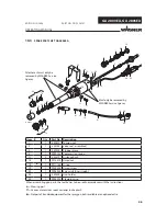
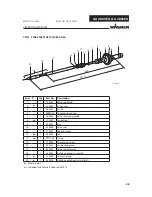
GA 2800EA, GA 2805EA
G A28
00
E A
77
78
70
71
72
73
74
75
76
23
41
31
84
85
11
49
27
15
22 58
59
39
3
4
1
19
67
2
80
83
81
82
62
55
90
89
93
79
48
36
24
14
61
14
24
88
B_00157
OPERATING MANUAL
EDITION 12/2008
PART NO. DOC350731
Item
K
Qty
Part No.
Description
1
1
350507
Tension nut
2
1
350108
Valve rod , assembled
3
1
350300
Stopper piece
4
1
9999143
Compression spring
11
2
350319
Distance bush
14
1
9913015
Union nut
15
◆
1
9971164
O-ring
19
1
9902505
Union screw
22
1
9998254
Screw-in fi tting, straight
23
1
350309
Gun holder
24
1
9998290
Clamping ring
27
1
353362
Material connection
When assembling gun parts, the Loctite has to be used in accordance with the instructions
◆
= Wearing part
▼
= Various dimensions see accessories in chapter 9
●
= Not part of standard equipment for the spray gun, but is available as an optional extra
Attachment must
only be removed
by WAGNER Service
Agency
Must only be removed by
WAGNER Service Agency
10.2
SPARE PARTS LIST GA 2800EA


