20
GA 4000ACIC
N
B_03051
A
F
I
G
H
B
D
J
B_03052
C
L
E
K
M
OPERATING MANUAL
EDITION 06/ 2011
PART NO. DOC2312956
4.4
FUNCTIONAL DESCRIPTION
4.4.1
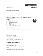
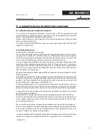
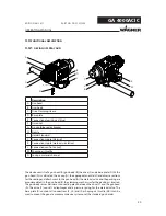
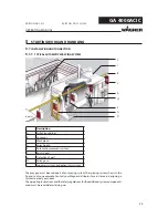
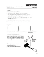
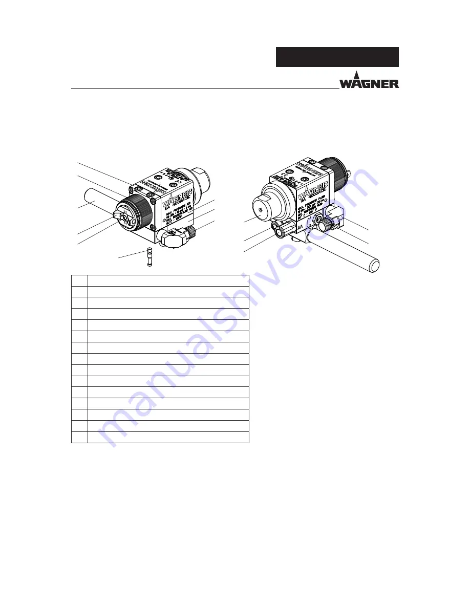
DESIGN OF SPRAY GUN
Description
A
Gun head
B
Gun body
C
Drive Clamping sleeve
D
Base plate
E
Connection atomizing air (blue)
F
Union nut
G
Air cap (blue, red or bronze)
H
Nozzle
I
Holder Standard
J
Connection nipple (Material)
K
Connection nipple (material circulation)
L
Connection control air (red)
M
Shaping air throttle
N
Lock pin material channel
The device consists of a gun head (A), gun body (B), the drive (C) and a base plate (D). At the
gun head (A) is cultivated the air cap (G), the appropriate nozzle (H) and diverse sections
for the sealing and attachment. In the gun head (A) the material valve and the packing are
accommodated. In the gun body (B) the clamping mechanism for the packing is inserted.
The gun body serves besides as connecting piece between the drive (C) and the gun head
(A). The drive (C) consists a diaphragm and a pressure spring for the material valve. The
base plate (D) contains all connections (E, J, K) and the shaping air throttle (M). It can be
used to mount the gun at a movement device system or at the standard gun holder.

