21
GA 4000ACIC
!!3!
#!
3!
!!
-
#
"?
B_03069
ME
B
D
A
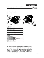
4x 4 Nm; 2.95 lbft
M
B_03489
B
D
M
J
A
ME
MR
4x 4 Nm; 2.95 lbft
OPERATING MANUAL
EDITION 06/ 2011
PART NO. DOC2312956
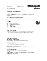
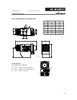
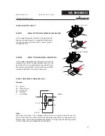
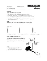
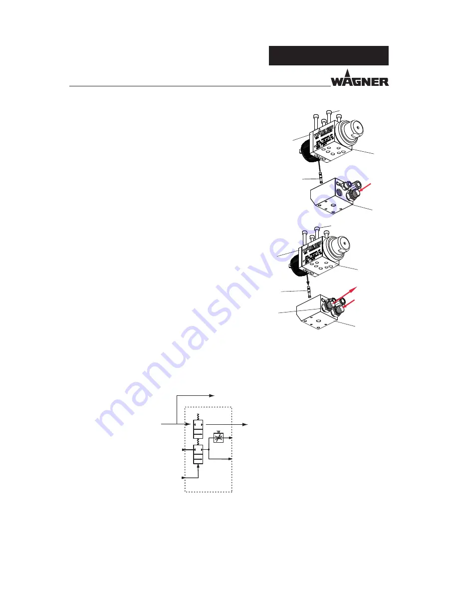
Diagram:
SA = Fan air
AA = Atomizing air
CA = Control air
M =
Material
C =
Circulation
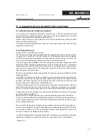
Open:
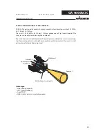
The piston in the drive is then charged with control air and moves toward the rear. This
ensures that the air valve which releases the shaping and atomizing air is opened fi rst. The
material valve is then opened mechanically delayed. In this position, the coating material
which is under pressure is applied to the workpiece.
Nozzle
4.4.3
FUNCTIONS OF THE SPRAY GUN
4.4.2
MODE “NC” AND “C”
4.4.2.2
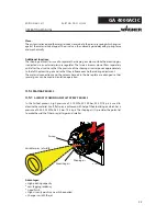
MODE “C” WITH MATERIAL CIRCULATION
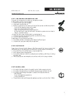
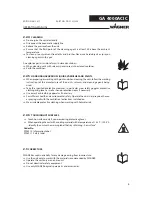
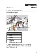
In this mode of operation the locking pin (M) must be
removed from the left or right material channel in the
gun head (A). Screw on additional connection fi tting (J).
The material entrance (ME) and the material return (MR)
are freely selectable in this mode of operation.
In this mode of operation the left or the right material
channel in the gun head (A) is locked by the locking pin
(M) and the material entrance (ME) is always lying on
the opposite side
4.4.2.1
MODE “NC” WITHOUT MATERIAL CIRCULATION

