36
GA 4000ACIC
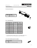
B_03058
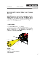
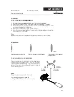
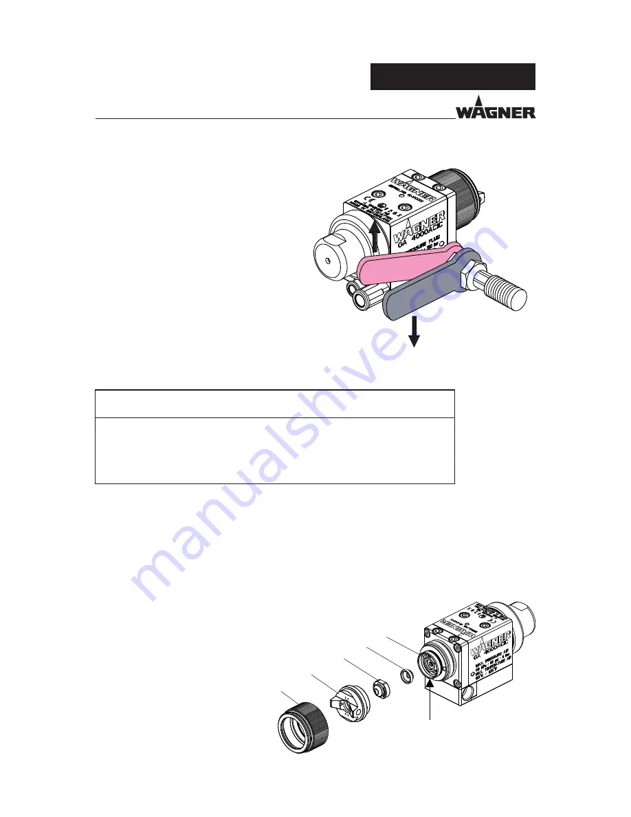
SW17 mm
SW19 mm
B_03062
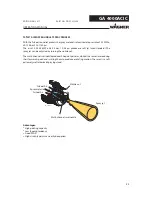
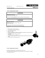
B
E
D
C
F
A
OPERATING MANUAL
EDITION 06/ 2011
PART NO. DOC2312956
1. Finishing work and cleaning.
2. Relieve the pressure of gun and unit and remove
the detergent supply.
3. Secure gun (Remove the control air hose).
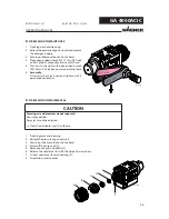
4. Place open-ended wrench SW 17 mm; 0.67 inch
on fl ats of paint connection and counter hold.
5. Turn nut to the right with open-ended wrench
SW 19 mm; 0.75 inch and unscrew material hose.
6.
Assembly:
Fit material hose by hand and tighten with 2
open-ended wrenches.
1. Finishing work and cleaning.
2. Relieve the pressure of gun and unit.
3. Secure gun (Remove the control air hose).
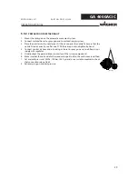
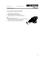
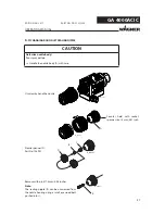
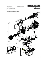
4. Screw off the union nut (A).
5. Remove air cap (B) and nozzle (C).
6. Release the nozzle seal (D) with the help of a screwdriver.
7. Fit new nozzle seal to valve housing (E).
8. Assemble in reverse order.
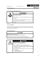
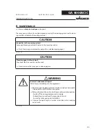
CAUTION
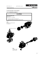
Forming air and atomizer air not separate!
Poor spray pattern
Spray jet cannot be adjusted
Treat the distributor seal (F) with care.
SIHI_0030_GB
6.2
REPLACING THE PAINT HOSE
6.3
REPLACING THE NOZZLE SEAL

