

12
VERSION 05/2018
ORDER NUMBER DOC 2312956
GA 4000ACIC
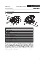
4
BASIC SAFETY INSTRUCTIONS
4.1
SAFETY INSTRUCTIONS FOR THE OPERATOR
Keep this operating manual at hand near the device at all times.
Always follow local regulations concerning occupational safety and accident
prevention.
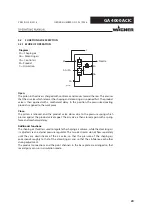
4.1.1 ELECTRICAL DEVICES AND EQUIPMENT
Electric shock hazard!
Danger to life from electric shock.
Prepare device in accordance with the local safety requirements with regard to the
operating mode and ambient influences.
May only be maintained by skilled electricians or under their supervision. With open
housings, the mains voltage poses a danger.
Operate device in accordance with the safety regulations and electrotechnical
regulations.
Must be repaired immediately in the event of problems.
Decommission if it poses a hazard or is damaged.
Must be de-energized before work is commenced. Inform personnel about planned
work. Observe electrical safety regulations.
Ground all devices to a common grounding point.
Only operate the device with a properly installed socket with a protective ground
wire connection.
Keep liquids away from electrical devices.
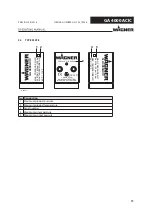
Summary of Contents for GA 4000ACIC-S
Page 1: ...Version 05 2018 GA 4000ACIC S GA 4000ACIC R AirCoat Automatic spray gun II 2G X B_06647...
Page 2: ......
Page 66: ......
Page 67: ......


