background image

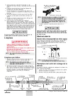
Cleanup

• Release system and spray gun pressure before

cleaning or performing maintenance on the gun.

• Use only the cleaning solvent recommended by the

material manufacturer.

• Never spray into an enclosed vessel (this will create

an explosive gas / air mixture).

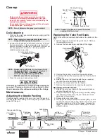
Daily cleaning

1. Flush out the spray gun material tube thoroughly with the

appropriate solvent.

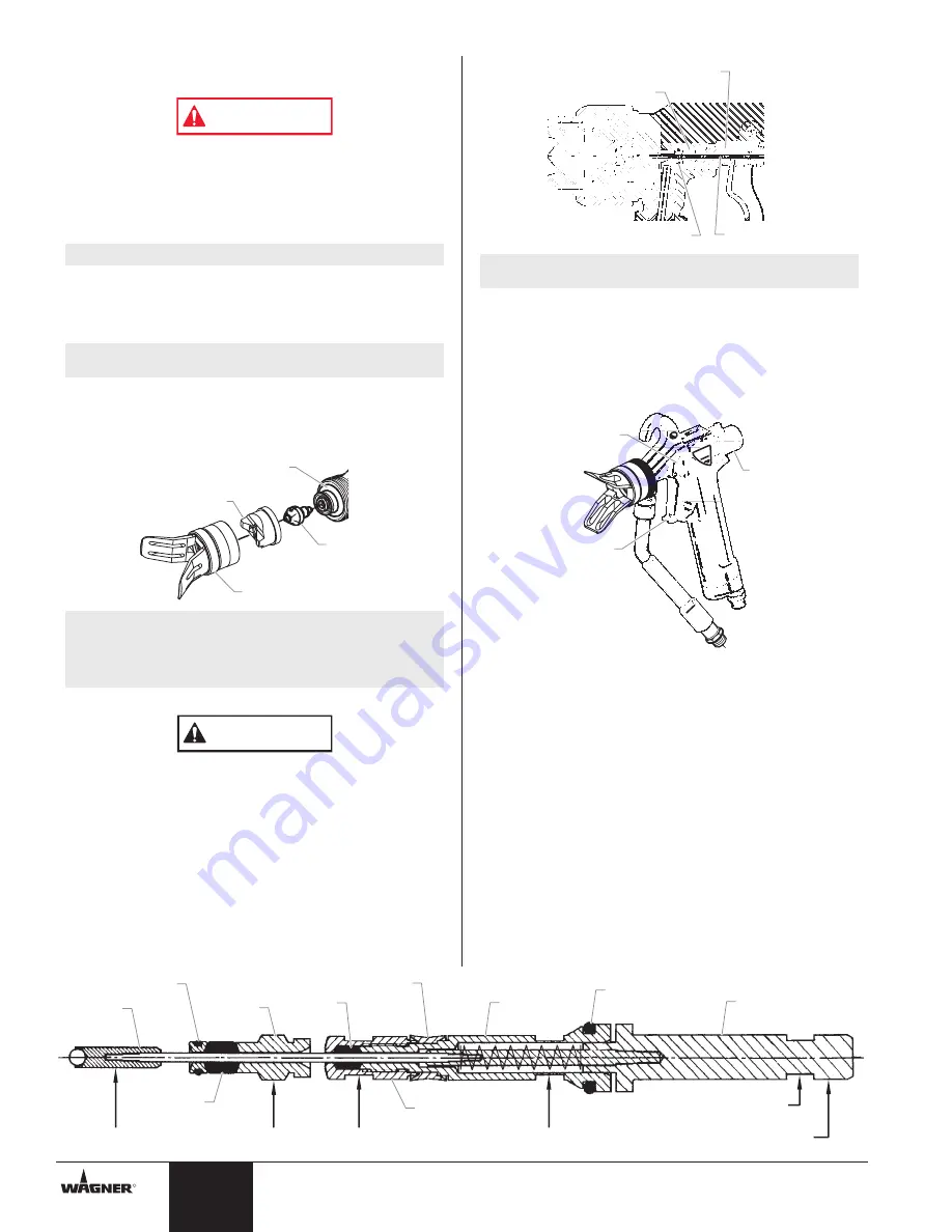
2. Unscrew the tip guard and remove the air cap.  Take out

the tip and immerse in the appropriate solvent until all
traces of material are dissolved.  Remove the tip and  put
into the appropriate solvent for 1 to 2 days until all
material residues are gone.

4. Clean the spray gun body using a brush.

Hold spray gun downward or horizontal while cleaning the
spray gun.  Cleaning solvent must not be allowed to enter
the air channels as this will cause swelling of the O-rings.

Maintenance

Adjusting the Needle Packing

If material begins leaking at the valve rod, flush the gun and
carefully tighten the packing screw using the gun spanner that
came with this gun.

CAUTION

NOTE: Handle the tip with care.  Do not clean it with

sharp metal objects.  Use tip cleaning brush
(P/N 9997001) only.  If necessary, use
corresponding tip cleaning needle (P/N
8612001, set of 12) for cleaning tip.

Air channels behind 

distributor ring

Air Cap

Tip

Tip Guard

NOTE: When using two component materials more

frequent flushing may be required.

NOTE: Do not immerse the spray gun in solvent.

WARNING

4

© Wagner.  All rights reserved.

Replacing the Valve Rod Seals

Refer to the valve rod complete illustration at the bottom of the
page.

1. Pull the trigger and unscrew the gun lock nut.  Remove

the compression spring.

2. Remove the flat-head screw and take off the trigger.

3. Unscrew the packing screw from the sealing sleeve.
4. Carefully withdraw the complete valve rod from the back

of the gun.

5. Holding the valve rod mounting with the gun spanner,

unscrew the valve ball holder using pliers.

6. Remove the components from the needle.
7. Remove the compression ring and needle packing.

Repairing Air Valve Seals

1. Holding the valve push-rod with the universal spanner,

unscrew the push-rod cap.

2. Change compression ring (with O-ring), needle packing,

rear seal, and, if necessary, the push-rod seal and air
valve seal of the air valve

3. Reassemble in reversed order
4. The trigger must be pulled before replacing the gun lock

nut and the compression spring. Screw on the nut until a
noticeable resistance is felt at the trigger.  Release the
trigger.  The lever travel is now correctly set for air and
material release.

Trigger

Flat-Head 

Screw

Gun 

Lock 

Nut

NOTE: If leaking continues, replace the needle

packing and the o-ring.

Needle Packing 

Packing Screw 

O-Ring

Valve Rod

English

R

Use pliers 

here

Unscrew 

here

Unscrew 

here

Hold with 

spanner here

Hold with 

spanner here

Hold to remove 

valve rod here

Valve Ball 

Holder

Packing 

Screw

Rear 

Seal

Push-Rod 

Seal

Air Valve 

Seal

Valve 

Push-Rod

Valve Rod 

Mounting

Push-Rod 

Cap

Needle 

Packing

Compression Ring

Summary of Contents for GM 2600 0179070

Page 1: ...n ais Espa ol 0104 2004 Wagner All rights reserved Form No 0551368A Printed in the U S A GM 2600 Air Assisted Airless Spray Gun Owner s Manual Manuel de l utilisateur Manual del propietario Model Numb...

Page 2: ...e advisable WARNING 2 Wagner All rights reserved The equipment and objects in and around the spray area must be properly grounded to prevent static sparks Use only conductive or grounded high pressure...

Page 3: ...e air assisted airless process high coverage capacity low fogging tendency fine finish high viscosity materials applied without problems higher tool life of the Brilliant tip adjustability of spray je...

Page 4: ...mmerse the spray gun in solvent WARNING 4 Wagner All rights reserved Replacing the Valve Rod Seals Refer to the valve rod complete illustration at the bottom of the page 1 Pull the trigger and unscrew...

Page 5: ...p and material being used refer to the Gun Filter Chart below and the AirCoat Tip Chart in the Accessories section Wagner All rights reserved 5 English R Troubleshooting Solution 1 Increase the materi...

Page 6: ...essures corporelles graves PR VENTION Un approvisionnement en air frais et une vacuation des gaz doivent tre assur s afin que l air entourant la zone de pulv risation soit libre de toute accumulation...

Page 7: ...po 216 mm Hauteur 9 8 po 250 mm Poids 1 lb 420 g Introduction Au cours du processus de pulv risation adjonction d air sans air le produit pulv riser est atomis une pression comprise entre 400 et 2 80...

Page 8: ...t Retirez la t te et mettez la dans le solvant appropri pendant 1 2 jours jusqu ce que tous les r sidus de produit aient disparu NOTA Si vous utilisez un produit deux composants un rin age plus fr que...

Page 9: ...haute pression sur le raccord d entr e du produit Tableau de filtres pour le pistolet N de pi ce Pour t tes de tailles Maille filtrante Couleur du corps du filtre 0034383 1 pc 0089960 2 pc 0 007 0 011...

Page 10: ...d est tica artefactos el ctricos llamas l mparas piloto objetos calientes y chispas provenientes de la conexi n y desconexi n de cables de alimentaci n y de interruptores de luces en funcionamiento No...

Page 11: ...nta el ancho del chorro del aerosol dependiendo del ajuste de la perilla de ajuste de aire Gracias al dise o f cil de limpiar de la punta y a la ausencia de agujeros de aire cerca de la salida de aire...

Page 12: ...es NOTA Es probable que cuando se usen dos materiales de componentes se necesiten enjuagues m s frecuentes NOTA No sumerja la pistola pulverizadora en solvente ADVERTENCIA PRECAUCION 12 Wagner Todos l...

Page 13: ...8 Vuelva a fijar la manguera de alta presi n en el adaptador de admisi n de material Tabla de filtros de pistola N mero de pieza Para los tama os de puntas Malla del filtro Color del cuerpo de filtro...

Page 14: ...s article 16 du Tableau des t tes AirCoat qui se trouve dans la section du manuel traitant des accessoires NOTA Consulte la Tabla de puntas AirCoat en la secci n Accesorios de este manual para tama os...

Page 15: ...1 33 9971182 Joint torique 1 34 0179341 Presse toupe de pointeau 1 35 0179696 Ensemble du chapeau de la tige de pouss e comprend les l ments 51 et 52 1 36 0179339 Joint de tige de pouss e 1 37 017933...

Page 16: ...0 009 40 6 75 180 rojo 0143609 0 009 60 8 75 180 rojo 0143111 0 011 10 4 180 rojo 0143211 0 011 20 5 180 rojo 0143411 0 011 40 7 5 180 rojo 0143511 0 011 50 8 25 180 rojo 0143113 0 013 10 4 100 amaril...

Reviews: