


13
GM 4100AC
B_02663
A
B
CCC
OPERATING MANUAL
EDITION 12/2008
PART NO. DOC394821
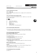
4.2.4
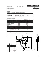
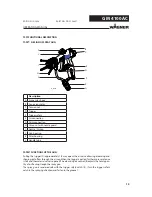
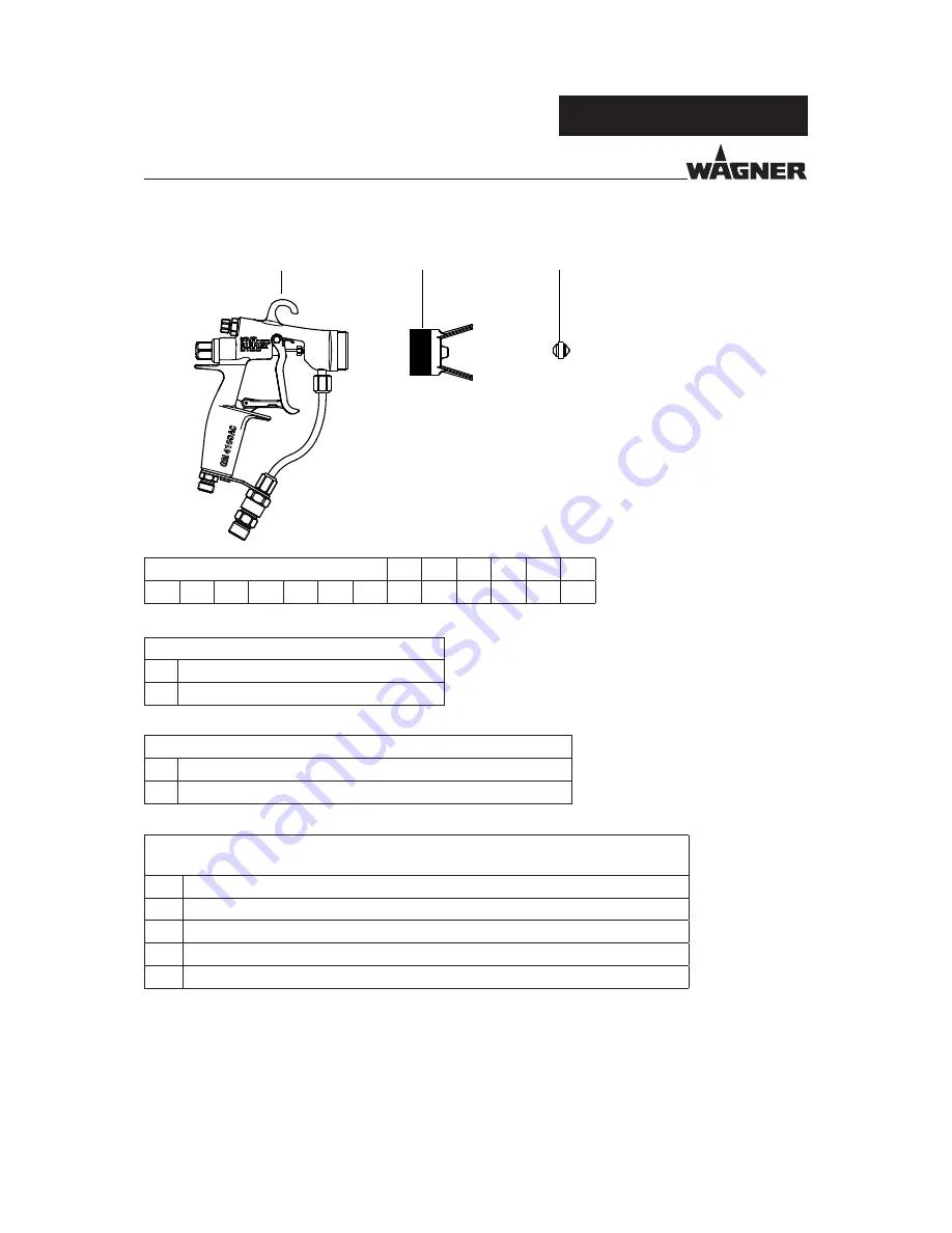
SPRAY GUN CONFIGURATION
Basis number GM 4100AC
-
A
B
C
C
C
-> Key
0
3
9
4
0
1
0
-
1
1
4
1
1
-> For example: Part number
Table A: Maxi. material pression selection
1
160 bar; 16 MPa; 2320 psi
2
250 bar; 25 MPa; 3625 psi
Table B: Air cap selection
1
Suitable for low viscosity paints (red)
2
Suitable for high viscosity paints (blue)
Table CCC: AirCoat nozzle selection ACF3000
CCC = the last three digits of the article number -> 0379CCC
107
1 = spray angle x 10 = 10
0
. 07 = diameter of bore in mm/1000 (0.007 mm)
411
4 = spray angle x 10 = 40
0
. 11 = diameter of bore in mm/1000 (0.011 mm)
317
3 = spray angle x 10 = 30
0
. 17 = diameter of bore in mm/1000 (0.017 mm)
625
6 = spray angle x 10 = 60
0
. 25 = diameter of bore in mm/1000 (0.025 mm)
835
8 = spray angle x 10 = 80
0
. 35 = diameter of bore in mm/1000 (0.035 mm)
The complete fl at-jet nozzle range is described in chapter 9.2.


