background image

31

GM 4100AC 

B_02270

14 (F)

13

36

33

?

?

?

?

OPERATING MANUAL

EDITION 12/2008

PART NO.  DOC394821

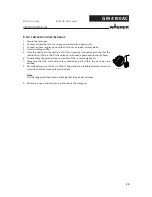
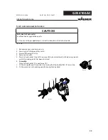
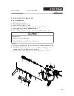
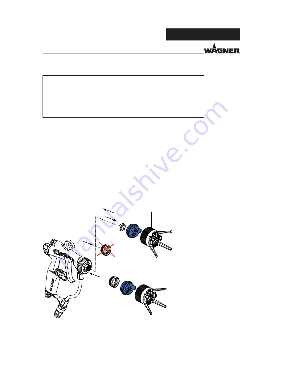
1.  Finishing work and cleaning.
2.  Relieve spray gun and unit pressure.
3.  Secure gun with trigger safety catch.
4.  Unscrew the union nut with nozzle guard (33).
5.  Remove air cap (36) and nozzle (13).
6.  Remove defective sealing ring (14/F) with the help of pipe tongs or with a large 

screwdriver.

7. 

Assembling:

 Fit new distributor seal (14/F) to air cap (36).

8.  Place air cap in body of gun together with sealing ring (14).
9.  Attach union nut (33) and screw in until the sealing ring snaps into place in the 

mounting groove (snap hearable).

10. 

Demount union nut (33) and air cap (36) and complete spray gun according to 
paragraph 5.4.3

.

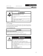
CAUTION

Forming air and atomizer air not separate!

Poor spray pattern
Spray jet cannot be adjusted

œ

Treat the distributor seal (F) with care.

SIHI_0030_GB

6.6 

REPLACING THE „AIR“ SEALING RING

Summary of Contents for GM 4100AC

Page 1: ...GM 4100AC B_02254 II 2G X Atex 95 AirCoat Spray gun for flat and round jet nozzles Edition 12 2008 Translation of the original Operating manual ...

Page 2: ......

Page 3: ...ture 9 2 4 4 Maximum surface temperature 9 2 5 German regulations and guidelines 9 3 PRODUCT LIABILITY AND WARRANTY 10 3 1 Important notes on product liability 10 3 2 Warranty 10 3 3 CE conformity 11 4 DESCRIPTION 12 4 1 Fields of application using in accordance with the instructions 12 4 1 1 Processing materials 12 4 2 Extent of delivery 12 4 2 1 Variant for application range up to 16 MPa 160 bar...

Page 4: ...5 6 2 Replacing the material hose or air hose 26 6 3 Changing or cleaning Filter insert 27 6 4 Replacing parts on the valve rod 28 6 4 1 Disassembling 28 6 4 2 Replacement of valve rocker seals 29 6 4 3 Replacing the rod seal 35 29 6 4 4 Assembling 29 6 5 Replacing the nozzle seal 30 6 6 Replacing the air sealing ring 31 7 TROUBLE SHOOTING AND SOLUTION 32 9 ACCESSORIES 33 9 1 Round jet nozzle cap ...

Page 5: ...s material damage Caution a possibly hazardous situation Non obser vance can result in minor injury Note provide information on particular characteristics and how to proceed Caution a possibly hazardous situation Non obser vance can cause material damage SIHI_0100_GB DANGER This line warns of the hazard Possible consequences of failing to observe the warning instruc tions The signal word points ou...

Page 6: ...IVE PARTS NFORM STAFF ABOUT PLANNED WORK OBSERVE ELECTRICAL SAFETY REGULATIONS NSURE THAT THE UNIT IS OPERATED AND REPAIRED ONLY BY TRAINED PERSONS NSURE THAT THE mOOR OF THE WORKING AREA IS ANTI STATIC IN ACCORDANCE WITH 0ART e MEASUREMENT IN ACCORDANCE WITH NSURE THAT ALL PERSONS WITHIN THE WORKING AREA WEAR ANTI STATIC SHOES E G SHOES WITH LEATHER SOLES NSURE THAT DURING SPRAYING PERSONS WEAR A...

Page 7: ... immediately Avoid danger of injury through recoil forces Ensure that you have a firm footing when operating the spray gun Only hold the spray gun briefly in any one position Electrostatic charges can occur on the unit due to the electrostatic charge and the flow speed involved in spraying These can cause sparks and flames upon discharge Ensure that the unit is always earthed Earth the work pieces...

Page 8: ...THE PAINTS SOLVENTS AND CLEANING AGENTS BEING USED 4AKE THE SPECIlED PROTECTIVE MEASURES IN PARTICULAR WEAR SAFETY GOGGLES PROTECTIVE CLOTHING AND GLOVES AS WELL AS HAND PROTECTION CREAM IF NECESSARY 5SE A MASK OR BREATHING APPARATUS IF NECESSARY OR SUFlCIENT HEALTH AND ENVIRONMENTAL SAFETY PERATE THE UNIT IN A SPRAY BOOTH OR ON A SPRAYING WALL WITH THE VENTILATION EXTRACTION SWITCHED ON 7EAR SUIT...

Page 9: ...ARKS CAN FORM IF THE UNIT COMES INTO CONTACT WITH METAL N AN EXPLOSIVE ATMOSPHERE O NOT KNOCK OR PUSH THE UNIT AGAINST STEEL OR RUSTY IRON O NOT DROP THE SPRAY GUN 5SE ONLY TOOLS THAT ARE MADE OF A PERMITTED MATERIAL GNITION TEMPERATURE OF THE COATING MATERIAL NSURE THAT THE IGNITION TEMPERATURE OF THE COATING MATERIAL IS ABOVE THE MAXIMUM SURFACE TEMPERATURE EDIUM SUPPORTING ATOMIZING 4O ATOMIZE ...

Page 10: ... THE UNIT TO A LOCATION OTHER THAN THE ADDRESS OF THE PURCHASER 4HIS WARRANTY DOES NOT COVER DAMAGE CAUSED BY 5NSUITABLE OR IMPROPER USE FAULTY INSTALLATION OR COMMISSIONING BY THE PURCHASER OR A THIRD PARTY NORMAL WEAR NEGLIGENT HANDLING DEFECTIVE MAINTENANCE UNSUITABLE COATING PRODUCTS SUBSTITUTE MATERIALS AND THE ACTION OF CHEMICAL ELECTROCHEMICAL OR ELECTRICAL AGENTS EXCEPT WHEN THE DAMAGE IS ...

Page 11: ...ng up for cleaning with solvents for cleaning workpieces with solvents f BGI 740 Painting rooms and equipment g ZH 1 406 Guidelines for liquid ejection devices Note All titles can be ordered from Heymanns Publishing House in Cologne or of the Internet download Herewith we declare that the supplied version of GM 4100AC 16 MPa GM 4100AC 25 MPa Complies with the following guidelines 98 37 EG 94 9 EG ...

Page 12: ...t with a coating material with a temper ature greater than 43 C 109 4 F Identify the unit with a warning sticker Warning hot surface 4 2 2 VARIANT FOR APPLICATION RANGE UP TO 25 MPA 250 BAR 3625 PSI Qty Part No Description 1 394012 GM 4100AC 25 MPa NPSM1 4 Paint connection 4 2 1 VARIANT FOR APPLICATION RANGE UP TO 16 MPA 160 BAR 2320 PSI Qty Part No Description 1 394002 GM 4100AC 16 MPa NPSM1 4 Pa...

Page 13: ...ints red 2 Suitable for high viscosity paints blue Table CCC AirCoat nozzle selection ACF3000 CCC the last three digits of the article number 0379CCC 107 1 spray angle x 10 100 07 diameter of bore in mm 1000 0 007 mm 411 4 spray angle x 10 400 11 diameter of bore in mm 1000 0 011 mm 317 3 spray angle x 10 300 17 diameter of bore in mm 1000 0 017 mm 625 6 spray angle x 10 600 25 diameter of bore in...

Page 14: ...xi material pressure MPa psi bar 16 2320 160 25 3625 250 Paint hose connection Inches NPSM1 4 Air connection Inches G1 4 Filter Mesh 100 Weight g oz 437 15 4 pH range of the material pH 3 5 9 0 Maxi temperature material C F 55 131 Maxi temperature air C F 43 109 Sound level at 0 3 MPa 3 bar 43 5 psi air pressure and 11 MPa 110 bar 1549 psi material pressure dB A 82 Filter types see chapter 9 6 A r...

Page 15: ...CTIONS OF THE GUN Pulling the trigger D approximately 1 2 way opens the air valve allowing atomising and shaping air to flow through the air cap When the trigger is pulled further more resistance is felt and the material valve is opened The atomising air control B adjusts the total quan tity of air flowing trough the spray gun The spray gun is rendered safe with the trigger safety catch E Turn the...

Page 16: ...stem It is not an actual system design Contact your Wagner distributor for assistance in designing a system to meet your needs The operating instructions and the safety regulations for the additional system compo nents used must be read before starting up 5 1 INSTALLATION AND CONNECTION WARNING Incorrect installation operation Risk of injury and damage to equipment When putting into operation and ...

Page 17: ...ying wall with the venti lation extraction switched on Observe national and local regulations for the outgoing air speed SIHI_0028_GB CAUTION Impurities in the spraying system Spray gun blockage materials harden in the spraying system Flush the spray gun and paint supply with a suitable cleaning agent SIHI_0001_GB SIHI_0029_GB DANGER Bursting hose bursting threaded joints Danger to life from injec...

Page 18: ...cal x Sec mPas Please also read the technical data sheet for the paint for optimal processing viscosity adjustment and intermixing of the material 7 2 ISCHARGE OF ELECTROSTATICALLY CHARGED COMPONENTS IN ATMO SPHERES CONTAINING SOLVENTS XPLOSION HAZARD FROM ELECTROSTATIC SPARKS OR mAMES ARTH ALL UNIT COMPONENTS ARTH THE WORKPIECES BEING PAINTED 3 WARNING Heavy paint mist if earthing is insufficient...

Page 19: ...s Always point the spray gun down when cleaning Ensure that neither paint nor cleaning agent enters the air duct SIHI_0005_GB SIHI_0065_GB WARNING Unintentional putting into operation Risk of injury Before all work on the unit in the event of work interruptions and functional faults Switch off the energy compressed air supply Relieve the pressure from the spray gun and unit Secure the spray gun ag...

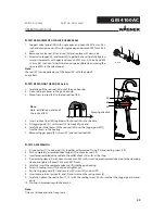
Page 20: ...air cap over the nozzle ensuring that the location flats X are in line Fit the union nut with nozzle guard and tighten by hand 6 Visually check the permissible pressures for all the system components 7 Make sure that the unit and all other conductive parts within the work area are earthed 8 Set material pressure 100 bar 10 MPa 1450 psi and use a suitable medium solvent or water to check that conne...

Page 21: ...re below 5 Use the shaping air controller on the gun to adjust the shaping air to atomizer air ratio until the optimal spray pattern is achieved Note Repeat point 4 and 5 until the optimum spray pattern is reached process iterative Spray pattern No atomizing air Too little atomizing air Correct amount of air 5 4 2 ADJUSTING THE SPRAY PATTERN The spray pattern can be adjusted to suit the object bei...

Page 22: ...zle C out of the air cap B by hand and brush with cleaning solvent until all remaining paint has been dissolved 6 Assembly Place AirCoat nozzle C in nozzle seal D 7 Fit the air cap B over the nozzle C ensuring that the location flats X are in line 8 Fit the union nut with nozzle guard A and tighten by hand CAUTION Defective AirCoat nozzle Insufficient paint application quality Do not use sharp edg...

Page 23: ...hat the location flats X are in line 7 Fit the union nut with nozzle guard A over the air cap B onto the spray gun and tighten by hand 8 Switch the material pressure back on 9 Turn the safety catch to the spraying position and briefly pull trigger 10 When the blockage has been flushed out secure the gun with safety catch 11 Relieve spray gun and unit pressure 12 Unscrew the union nut with nozzle g...

Page 24: ... Never immerse the spray gun in cleaning agent SIHI_0066_GB SIHI_0004_GB WARNING Incorrect maintenance repair Risk of injury and damage to the equipment Repairs and part replacement may only be carried out by spe cially trained staff or a WAGNER service center Before all work on the unit and in the event of work interrup tions Switch off the energy compressed air supply Relieve the pressure from t...

Page 25: ...n with trigger safety catch 8 Clean gun body with a cleaning agent recommended by the manufacturer and dry with a cloth 6 1 FINISHING WORK AND CLEANING DANGER Exploding gas air mixture Danger to life from flying parts and burns Never spray into a closed container Earth the container SIHI_0008_GB CAUTION Cleaning agent in the air duct Functional faults caused by swollen seals Always point the spray...

Page 26: ... SW D and unscrew material hose Air hose 4 Place open ended wrench SW D on flats of air connection and counter hold 5 Turn nut to the right with open ended wrench SW C and unscrew air hose 6 Assembly Fit the material hose respectively air hose by hand and tighten with 2 open ended wrenches Counter hold Note Do not unscrew the filter housing The nut must only be unscrewed by WAGNER Serv ice Agency ...

Page 27: ...ded wrench A on flats of filter housing 30 and counter hold 5 Turn nut to the right with open ended wrench B and unscrew pivot joint 32 with material hose 6 Remove the material filter 31 7 Clean the filter housing 30 filter socket 32 and edge filter with cleaning agent 8 Assembly Fit the cleaned or new edge filter 31 into the filter socket 32 9 Fit filter socket with the material hose by hand and ...

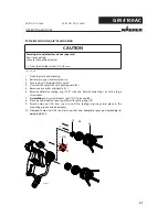
Page 28: ...move together with nut 20 6 Remove trigger 21 7 Loosen sealing screw 10 with single open end wrench SW 7 mm 0 28 inches CAUTION Unsuitable tool Damage to seals and sealing surfaces Do not hold the valve rod with pliers or a similar tool SIHI_0006_GB 8 Carefully pull the complete valve rod B together with sealing screw out of the gun housing A toward the rear 9 Hold the clamping sleeve 4 with open ...

Page 29: ...h inserted O ring 12 and sealing screw 10 2 Push completely assembled valve tappet 19 onto valve rod 14 3 Insert preassembled valve rod into the collet chuck 18 as far as the stop 4 Fix clamping sleeve 4 with wrench size 6 mm 0 24 inch screw the preassembled valve rod to the clamping sleeve and tighten Socket SW 2 mm 0 079 inch 5 Carefully insert the complete valve rod B into the gun housing 6 Scr...

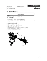
Page 30: ...nion nut with nozzle guard 33 5 Remove air cap 36 and nozzle 13 6 Carefully release the nozzle seal 17 with the help of a screwdriver 7 Fit new nozzle seal to valve housing 16 8 Continue assembly in the reverse order CAUTION Defective nozzle seal Material sprays into the air cap next to the nozzle Risk of contamination Do not clean the nozzle seal with sharp edged objects Replace the nozzle seal i...

Page 31: ...gs or with a large screwdriver 7 Assembling Fit new distributor seal 14 F to air cap 36 8 Place air cap in body of gun together with sealing ring 14 9 Attach union nut 33 and screw in until the sealing ring snaps into place in the mounting groove snap hearable 10 Demount union nut 33 and air cap 36 and complete spray gun according to paragraph 5 4 3 CAUTION Forming air and atomizer air not separat...

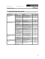
Page 32: ...erial viscosity to high Dilute spraying material acc to manufacturer s instructions Partial nozzle blockage Nozzle cleaning 5 4 5 Wrongly adjusted atomizing air Readjust the atomizing air 5 4 1 Air cap faulty blocked holes damaged seal Clean or replace air cap 5 4 5 Wrong air cap type Replace as required air cap solvent water based 4 2 4 Valve rod leaks Paint or air path Paint seal packing damaged...

Page 33: ... 17 0 48 480 approx 250 9 84 132727 Nozzle insert R18 18 0 53 530 approx 250 9 84 132728 Nozzle insert R19 19 0 59 590 approx 250 9 84 132729 Nozzle insert R20 20 0 65 650 approx 250 9 84 132730 Nozzle insert R21 21 0 71 710 approx 250 9 84 132731 Nozzle insert R22 22 0 77 770 approx 250 9 84 Volume flow l min cc min water at approx 10 MPa 100 bar 1450 psi Jet width in mm inch at a distance of 30 ...

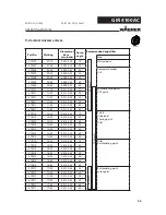
Page 34: ...813 13 80 0 013 0 33 800 379115 15 10 0 015 0 38 100 379215 15 20 0 015 0 38 200 379315 15 30 0 015 0 38 300 379415 15 40 0 015 0 38 400 379515 15 50 0 015 0 38 500 379615 15 60 0 015 0 38 600 379815 15 80 0 015 0 38 800 379217 17 20 0 017 0 43 200 379317 17 30 0 017 0 43 300 379417 17 40 0 017 0 43 400 379517 17 50 0 017 0 43 500 379617 17 60 0 017 0 43 600 379817 17 80 0 017 0 43 800 B_02280 OPE...

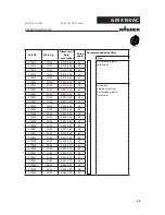
Page 35: ...0 379625 25 60 0 025 0 64 600 379825 25 80 0 025 0 64 800 379427 27 40 0 027 0 69 400 379627 27 60 0 027 0 69 600 379827 27 80 0 027 0 69 800 379429 29 40 0 029 0 75 400 379629 29 60 0 029 0 75 600 379829 29 80 0 029 0 75 800 379431 31 40 0 031 0 79 400 379631 31 60 0 031 0 79 600 379831 31 80 0 031 0 79 800 379435 35 40 0 035 0 90 400 379635 35 60 0 035 0 90 600 379835 35 80 0 035 0 90 800 B_0228...

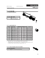
Page 36: ... connection G1 4 394926 Swivel for paint connection NPSM 1 4 with filter 100 mesh 364938 Swivel for air connection G1 4 3204605 Filter for swivel 100 mesh 3204604 Filter for swivel 60 mesh 9999002 Filter for swivel 200 mesh 9 4 SWIVELS AND FILTER 9 3 AIR CAPS Part No Description 394910 Air cap LV assy red for low viscosity paints 394911 Air cap HV assy blue for high viscosity paints ...

Page 37: ...nipple G1 4 outside thread for air hose extension 9 5 HOSES Part No Description 394100 Hose set AC Material DN3 Air DN6 Consisting of paint air and protective hose Paint NPS1 4 7 5 m 24 6 ft DN 3 mm ID 0 12 inch 27 MPa 270 bar 3916 psi Air G1 4 7 5 m 24 6 ft DN 6 mm ID 0 24 inch 0 8 MPa 8 bar 116 psi 394101 Hose set AC Material DN4 Air DN6 Consisting of paint air and protective hose Paint NPS1 4 7...

Page 38: ... all work LWAYS SUPPLY THE FOLLOWING INFORMATION TO ENSURE DELIVERY OF THE RIGHT SPARE PART 0ART UMBER DESCRIPTION AND QUANTITY 4HE QUANTITY NEED NOT BE THE SAME AS THE NUMBER GIVEN IN THE u1UANTITYh COLUMN 4HIS NUMBER MERELY INDICATES HOW MANY OF THE RESPECTIVE PARTS ARE USED IN EACH SUBASSEMBLY 4HE FOLLOWING INFORMATION IS ALSO REQUIRED TO ENSURE SMOOTH PROCESSING OF YOUR ORDER DDRESS FOR THE IN...

Page 39: ...ing 13 1 0379xxx 0379xxx AC nozzle see chapter 9 2 14 1 394339 394339 Sealing ring 15 1 9974245 9974245 O ring 16 1 394922 394922 Valve seat compl 17 1 394338 394338 Seal Nozzle 18 1 394330 394330 Chuck 19 1 394257 394257 Valve tappet compl 20 1 394318 394318 Nut 21 1 394310 394310 Trigger 22 1 394319 394319 Screw 23 1 394334 394334 Safety catch 24 1 9935088 9935088 Cylindrical shaft 31 1 3204605 ...

Page 40: ...4 84 19 10 11 12 82 A 6 1 80 55 56 57 58 59 60 61 62 63 OPERATING MANUAL EDITION 12 2008 PART NO DOC394821 Mounting materials Pos K Part No Description 80 9992831 Loctite 542 81 9992833 Loctite 638 green 82 9992590 Loctite 222 83 9992698 Vaseline white PHHV II 84 394342 Tool valve rod seal Detail A ...

Page 41: ... 57 1 132516 132516 Nozzle screw connection compl 58 1 132351 132351 Nozzle screwed connection holder 59 1 394308 394308 Union nut 60 1 394337 394337 Nozzle nut 61 1 132 132 Nozzle insert R various dimensions see chapter 9 1 1 62 1 394180 394180 Round jet nozzle cap see chapter 9 1 63 1 132922 132922 Nozzle screw connection compl 1 394940 394940 Service Set GM 4100AC Wearing part Included in servi...

Page 42: ...rielles wagner france fr Netherlands WAGNER SPRAYTECH Benelux BV Zonnebaan 10 NL 3542 EC Utrecht Telephone 31 0 30 241 4155 Telefax 31 0 30 241 1787 E Mail info wsb wagner nl Italy WAGNER COLORA S r l Via Fermi 3 I 20040 Burago di Molgora MI Telephone 39 039 625021 Telefax 39 039 6851800 E Mail info wagnercolora com Japan WAGNER Spraytech Ltd 2 35 Shinden Nishimachi J Daito Shi Osaka 574 0057 Tele...

Page 43: ......

Page 44: ...ERMANY 7 2 MB TTO ILIENTHAL 3TR 0OSTFACH ARKDORF 4ELEPHONE 4ELEFAX AIL SERVICE STANDARD WAGNER GROUP COM 3WITZERLAND 7 2 NDUSTRIESTRASSE 0OSTFACH LTSTËTTEN 4ELEPHONE 4ELEFAX AIL REP CH WAGNER GROUP CH WWW WAGNER GROUP COM 394821 ...

Reviews: