

60
OPERATING MANUAL
EDITION 05/2015
ORDER NUMBER DOC2319150
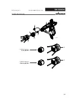
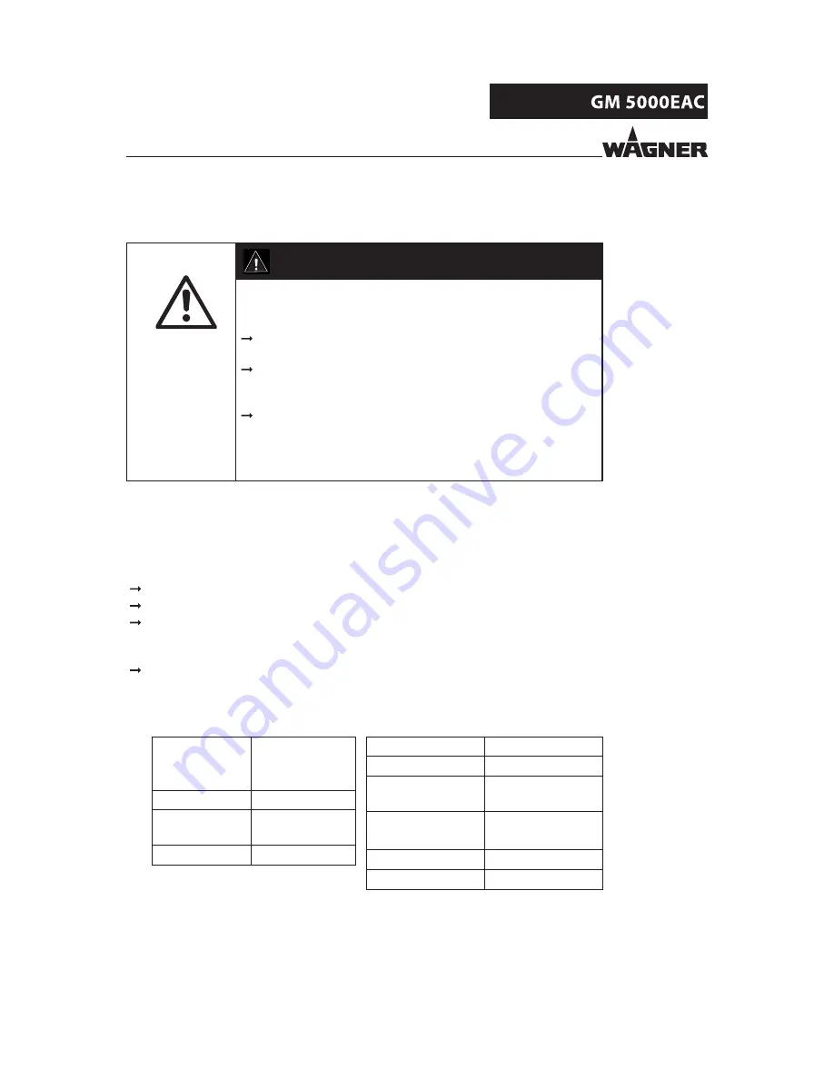
Bursting hose, bursting threaded joints!
Danger to life from injection of product and from fl ying parts.
Ensure that the hose material is chemically resistant to the
sprayed products and the used fl ushing agents.
Ensure that the spray gun, threaded joints, and product hose
between the device and the spray gun are suitable for the
generated pressure.
Ensure that the following information can be seen on the hose:
-
Manufacturer
- Permissible operating pressure
- Date of manufacture
DANGER
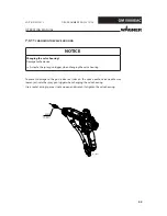
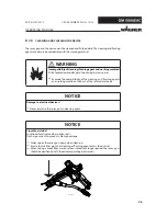
8.2.4
PRODUCT HOSES, TUBES AND COUPLINGS
The service life of the complete hoses between product pressure generator and application
device is reduced due to environmental infl uences even when handled correctly.
Check hoses, pipes, and couplings every day and replace if necessary.
Before every commissioning, check all connections for leaks.
Additionally, the operator must regularly check the complete hoses for wear and tear
as well as for damage at intervals that he/she has set. Records of these checks must
be kept.
Undamaged complete hoses are to be replaced when one of the two following
intervals has been exceeded:
– 6 years from the date of the hose crimping (see fi tting embossing).
– 10 years from the date of the hose imprinting.
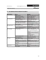
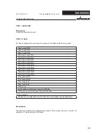
Fitting
embossing
Meaning
(if present)
xxx bar
Pressure
yymm
Crimping date
(year/month)
XX
Internal code
Hose imprinting
Meaning
WAGNER
Name / Manufacturer
yymm
Date of manufacture
(year/month)
xxx bar (xx MPa)
Pressure
e.g., 270 bar (27 MPa)
XX
Internal code
DNxx (e.g., DN10)
Nominal diameter
Summary of Contents for GM 50000EAC
Page 2: ......
Page 30: ...30 OPERATING MANUAL EDITION 05 2015 ORDER NUMBER DOC2319150...
Page 53: ...53 OPERATING MANUAL EDITION 05 2015 ORDER NUMBER DOC2319150...
Page 62: ...62 OPERATING MANUAL EDITION 05 2015 ORDER NUMBER DOC2319150...
Page 103: ...103 OPERATING MANUAL EDITION 05 2015 ORDER NUMBER DOC2319150...
Page 104: ...104 OPERATING MANUAL EDITION 05 2015 ORDER NUMBER DOC2319150...
Page 106: ...106 OPERATING MANUAL EDITION 05 2015 ORDER NUMBER DOC2319150...
Page 107: ......


