71
3
B_04791
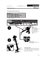
SW2
1Nm
X
6
7
B_04770
0.5 Nm
SW6
0.4 - 0.5 Nm
SW5
2
1
4
5
8
9
10
8
7
11
2
2
9
2
2
OPERATING MANUAL
EDITION 05/2015
ORDER NUMBER DOC2319150
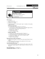
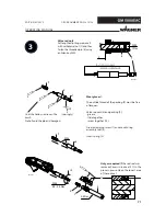
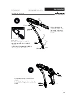
Valve rod unit
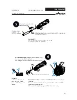
Set length adjusting measure X
with withdrawal nut (7) and then
fasten the threaded pin (6) using
an Allen key SW2.
Coat the hollow section with a
brush.
Note: Avoid the pin and hexagon.
(sparingly)
Wear gloves!
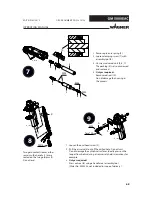
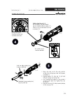
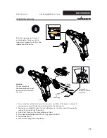
The outside thread of the packing (9) must be free
of lacquer.
Valve rod unit (8) and packing (9):
- grease,
- slide together,
- screw together (10).
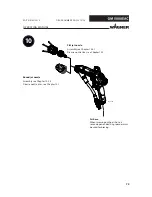
Grease clamping screw (1) and mount using
assembly tool (5).
Insert spring (4).
Only as required
(if the rod seal was
removed): press in rod seal (11). In the
process, press only on the lowest area
of the rod seal.
Summary of Contents for GM 50000EAC
Page 2: ......
Page 30: ...30 OPERATING MANUAL EDITION 05 2015 ORDER NUMBER DOC2319150...
Page 53: ...53 OPERATING MANUAL EDITION 05 2015 ORDER NUMBER DOC2319150...
Page 62: ...62 OPERATING MANUAL EDITION 05 2015 ORDER NUMBER DOC2319150...
Page 103: ...103 OPERATING MANUAL EDITION 05 2015 ORDER NUMBER DOC2319150...
Page 104: ...104 OPERATING MANUAL EDITION 05 2015 ORDER NUMBER DOC2319150...
Page 106: ...106 OPERATING MANUAL EDITION 05 2015 ORDER NUMBER DOC2319150...
Page 107: ......

