21
GM 5000EA
6
14
20
6
5
7
16
15
2
4
3
1
9
10
11
8
19
18
17
B _03232
22
12
21
B_03558
S
OPERATING MANUAL
EDITION 04/2016
ORDER NUMBER DOC2344499
5
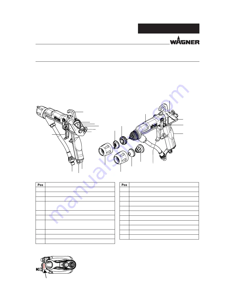
DESCRIPTION
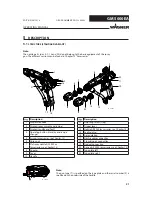
Description
1
Suspension hook
2
Display (spray current and recipe)
3
Display standby and fault
4
Operating button (standby and recipe
change)
5
Air cap (accessories: see Chapter 13)
6
Union nut
7
Flat spray nozzle AF 5000 x.x
(accessories: see Chapter 13)
8
Adapter
9
Cover
10
Handle
Description
11
Adjusting screw (stop)
12
Trigger lever
14
Nozzle AR 5000 (accessories: see Chapter 13)
15
Sealing plug
16
Air regulation
17
Electric cable connection
18
Atomizing air connection
19
Product connection
20
Air cap AR 5000 (accessories: see Chapter 13)
21
Type plate left
22
Type plate right
Note:
The nozzle parts (pos. 5; 7; 14 and 20) do not belong to the basic equipment of the spray
gun. The diff erent versions can be found in Chapter 13 "Accessories".
5.1
STRUCTURE (STANDARD VARIANT)
Note:
The gun type (T) is specifi ed on the type plate and the serial number (S) is
specifi ed on the underside of the handle.


