


18
GM 5000EAC
.
B_03558
S
B_03156
7
13
14
6
5
11
16
15
2
4
20
3
1
9
10
8
19
18
17
12
21
22
OPERATING MANUAL
EDITION 03/2012
PART NUMBER DOC 2319150
Note:
The gun type (T) on the type plate (21) and the serial number (S) on
the underside of the handle.
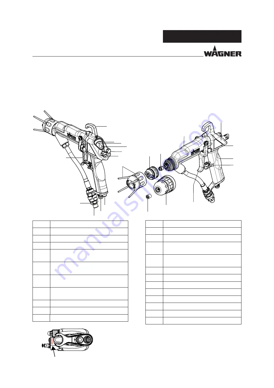
4.4
FUNCTIONAL DESCRIPTION
4.4.1
DESIGN OF SPRAY GUN (STANDARD VARIANT)
Note:
The nozzle parts (item 6; 7; 13 and 14) do not belong to the basic equipment of the spray
gun. The different versions can be found in Chapter 9 „Accessories“.
Item
Description
1
Hook
2
Display (spray current and recipe)
3
Display standby
4
Operating button
(standby and recipe change)
5
Protection against contact
with union nut
6
Air cap for fl at jet nozzle
(see Accessories chapter 9)
7
ACF 5000 fl at jet nozzle
(see Accessories chapter 9)
8
End piece
9
Cover
10
Handle
Item
Description
11
Trigger lock
12
Trigger
13
Round jet nozzle cap
(see Accessories chapter 9)
14
Round jet nozzle insert
(see Accessories chapter 9)
15
Lock plug
16
Air adjustment
17
Electrical cable connection
18
Atomizing air connection
19
Material connection
20
Filter housing with fi lter
21
Type plate left
22
Type plate right
Summary of Contents for GM5000
Page 2: ......
Page 3: ......
Page 4: ......
Page 5: ......
Page 6: ......
Page 7: ......
Page 8: ......
Page 9: ......
Page 10: ......
Page 11: ......
Page 12: ......
Page 13: ......
Page 14: ......
Page 15: ......
Page 16: ......
Page 17: ......
Page 18: ......
Page 19: ...Prime Spray Valve ASSY 0555901________...
Page 20: ......
Page 21: ......
Page 23: ......
Page 52: ......
Page 55: ......
Page 121: ...68 GM 5000EAC OPERATING MANUAL EDITION 03 2012 PART NUMBER DOC 2319150...
Page 122: ...69 GM 5000EAC OPERATING MANUAL EDITION 03 2012 PART NUMBER DOC 2319150...
Page 124: ......


