background image

29


HERO 23D / Hero 23 / SF 23 Pro

3.2


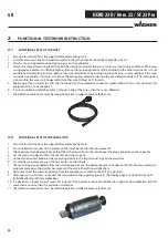
REPLACING A 400 V CORD SET 

1.  Ensure safe isolation from the supply before commencing work.

2.  First of all loosen the strain relief until the cable can be freely moved. 

3.  Disconnect the defective cable, noting the exact pin assignment. 

4.  Strip the new cable to the desired length, taking care not to damage the insulation of the individual wires. 

5.  First shorten wires L1, L2, L3 and N by 1.5 cm. This ensures that when there is a tensile load on the cable, the protective con-

ductor (PE) is disconnected last. 

6.  Now strip the individual wires to the desired length. 

7.  Now press the wire end ferrules on, making sure that the wires terminate fl ush with the sleeve and that no individual wires 

protrude.

8.  Now connect the cable in accordance with the pin assignment noted in point 3. Make sure that secure contact is achieved.

9.  Now tighten the strain relief - but not too much, as this could cause the cable or an individual wire to shear off . 

10.  After completing the repair a measurement in accordance with BGV A3 must be carried out, in order to ensure electrical 

safety and functionality. See chapter 1.4 

3.3


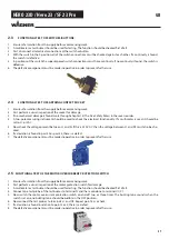
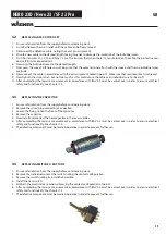
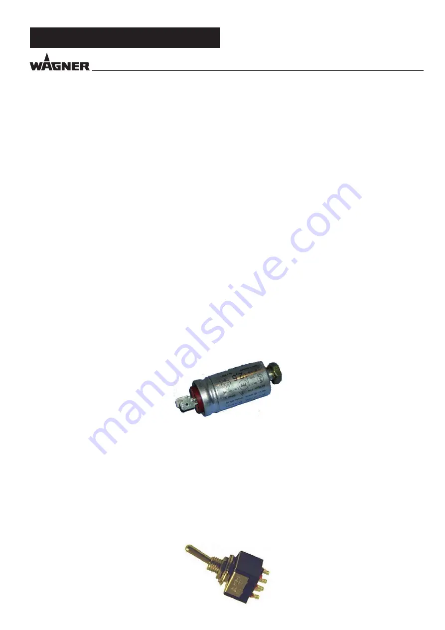
REPLACING THE CAPACITOR 

1.  Ensure safe isolation from the supply before commencing work. 

2.   Remove the wires (plug connector on capacitor). 

3.  Loosen the fi xing nut on the front of the capacitor. 

4.   Remove the capacitor. 

5.   Now install and connect the new capacitor in the reverse order.

6.  After completing the repair a measurement in accordance with BGV A3 must be carried out, in order to ensure electrical 

safety and functionality. See chapter 1.4. 

7.  The defective component must be made inoperative in order to prevent further use.

3.4


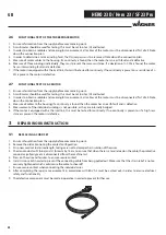
REPLACING SWITCHES / BUTTONS 

1.  Ensure safe isolation from the supply before commencing work. 

2.  Remove the individual wires at the switch, noting the contact confi guration. 

3.  Remove the switch, noting its installation position. 

4.  Install the new switch. 

5.  Establish the electrical connection, observing the contact confi guration of point 2. 

6.  After completing the repair a measurement in accordance with BGV A3 must be carried out, in order to ensure electrical 

safety and functionality. See chapter 1.4 

7.  The defective component must be made inoperative in order to prevent further use.


GB

Summary of Contents for HERO 23D

Page 1: ...Service manual with electrical repair instructions for electrically instructed persons of the J Wagner GmbH 2393847 F 02 2019 HERO 23D HERO 23 SF 23 PRO...

Page 2: ...y start up 1 Faulty units may not be used 2 Secure a Wagner spray gun with the securing lever at the trigger guard 3 Ensure earthing 4 Check the permissible operating pressure of the high pressure hos...

Page 3: ...4 2 Spare parts list high pressure filter accessory _____ 18 4 3 Spare parts list hopper________________________ 18 4 4 Spare parts list trolley_________________________ 19 4 5 Spare parts list sucti...

Page 4: ...njection Never point the spray gun at yourself other persons or animals Never use the spray gun without spray jet safety guard The spray jet must not come into contact with any part of the body In wor...

Page 5: ...n cause sparks and flames upon discharge The unit must therefore always be earthed via the electrical system The unit must be connected to an appropriately grounded safety outlet An electrostatic char...

Page 6: ...C Max viscosity 20 000 mPas Empty weight 27 kg Hydraulic oil filling quantity Hydraulics housing Gears grease 1 3 liter 45 g Max vibration at the spraygun lower than 2 5 m s Max sound pressure level 7...

Page 7: ...asurement 1 m distance from unit and 1 60 m abovefloor 12MPa 120bar operatingpressure reverberant floor Taiwan Voltage 110 V AC 60 Hz Fuses 16 A time lag Unit connecting line 6 m long 3 x 2 mm Max cur...

Page 8: ...nlet valve carefully 6 Clean the valve seat 4 with a cleaning agent and brush ensure that no brush hairs are left behind 7 Clean the seals 5 6 and check for damage Replace if necessary 8 Check all the...

Page 9: ...smantled the outlet valve regardless of which component you want to replace Note The seal 6 is located inside the paint sec tion 3 The groove in the seal 6 points outwards when replaced 1 7 2 3 4 5 6...

Page 10: ...g the power plug from the outlet 1 Remove the cover 1 by loosening the screws 2 Loosen the cable threaded joint 2 3 Loosen the wires 3 4 Replace the unit connecting line only an approved power cable w...

Page 11: ...fan cover Unit can t be ven tilated Ventilation possible in vertical position Not enough oil Check correct oil level Find reason for oil loss Maybe there is oil in the gear box Unit does not suck in M...

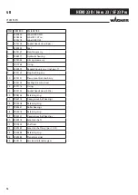
Page 12: ...cking screw 13 2393102 Outlet valve housing assy 14 2393105 O ring and sealing ring 15 2393106 Outlet valve assy incl pos 14 16 9900217 Hexagon head screw 17 9920134 Washer 18 2369435 Paint head 19 23...

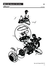
Page 13: ...13 HERO 23D Hero 23 SF 23 Pro Spare parts diagram HERO 23D 1 2 4 5 5 3 6 8 7 9 10 11 12 13 14 15 16 17 18 22 20 21 23 24 25 27 28 29 30 26 31 SPARE PARTS GB...

Page 14: ...242 2401124 Electric motor 230V China CE AUS incl pos 15 16 Electric motor 100V Japan incl pos 15 16 Electric motor 110V Taiwan incl pos 15 16 15 2393105 Fan assy 16 2393109 Fan cover assy 17 2390886...

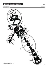
Page 15: ...15 HERO 23D Hero 23 SF 23 Pro SPARE PARTS Spare parts diagram HERO 23D 6 2391115 Rundschnur 1 2 3 4 5 6 8 9 11 13 18 19 20 7 12 15 17 10 16 14 21 22 GB...

Page 16: ...130 Stop bushing assy 10 2393131 Pressure control knob assy 11 2393132 Sealing screw and seal 12 2391115 O ring 13 2393133 Socket head screw 4 Stk 14 9998144 Retaining ring 15 9960113 Deep groove ball...

Page 17: ...17 HERO 23D Hero 23 SF 23 Pro 1 2 3 4 14 15 16 17 18 19 20 22 21 23 24 25 11 12 13 10 8 9 5 6 7 SPARE PARTS Spare parts diagram HERO 23D GB...

Page 18: ...48 0508 450 0508 449 Filter insert 60 meshes Optional Filter insert 100 meshes Filter insert 30 meshes 12 9994 245 Pressure spring 4 2 SPARE PARTS LIST HIGH PRESSURE FILTER Spare parts diagram high pr...

Page 19: ...7 9 11 9900118 Hexagon screw 12 2369545 Plate damping 13 9920102 Washer 14 9910208 Hexagon nut 15 2393119 Plate damping assy pos 11 14 16 2369556 Wheel 17 9994950 Wheel cap 18 2393121 Wheel assy pos...

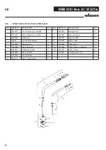
Page 20: ...800 1 12 2240022 Hose clamp 20 2 3 2230342 Filter assy 1 13 2240071 Hose 12 800 1 4 34602 Suction hose fitting 1 14 2240349 Return hose 1 5 2240009 Hexagon nut 1 15 2240345 Filter cover 1 6 2240083 Ho...

Page 21: ...hazards and special features The work instructions must include safe and correct replace ment of a connecting cable for example 1 2 SKILLED ELECTRICIAN FOR DEFINED TASKS In order to autonomously carr...

Page 22: ...les must be disconnected at all poles at the place of work before starting work This can be done by means of main switches expert removal of fuses disconnection of plug connectors etc Protecting again...

Page 23: ...ock in addition to the basic insulation Connection to the protective conductor system is not possible Appliances with this protection class are not permitted in Germany and Austria This protection cla...

Page 24: ...lanation L1 External conductor L2 External conductor L3 External conductor N Neutral conductor PE Protective conductor 3 Threephase AC voltage 1 8 EXPLANATION OF ELECTRICAL TERMS Rated current The rat...

Page 25: ...or is an earthed conductor which performs the function of protective conductor and neutral conductor simulta neously Active part of an electrical system An active part is a live part of an electrical...

Page 26: ...e is defective 7 The defective component must be made inoperative in order to prevent further use 2 2 FUNCTIONAL TEST OF THE CAPACITOR 1 Ensure safe isolation from the supply before commencing work 2...

Page 27: ...ed to check the electrical functionality If a multimeter is used it should be set to V or VAC 5 Now check the voltage present between L1 and N If this is 230 V AC then the voltage between L1 and PE mu...

Page 28: ...of all Note down the connection plan 4 Measure all cables to the housing if a continuity is found then the motor has an earth fault and is defective 5 Measurement of the individual windings is not po...

Page 29: ...ce with BGV A3 must be carried out in order to ensure electrical safety and functionality See chapter 1 4 3 3 REPLACING THE CAPACITOR 1 Ensure safe isolation from the supply before commencing work 2 R...

Page 30: ...ns from the motor protecting switch 4 The motor protecting switch can now be removed 5 Now install the new motor protecting switch and restore the electrical connection 6 After completing the repair a...

Page 31: ...in assignment 3 Now replace the motor 4 Observe the pin assignment noted in point 2 when connecting the individual wires Also ensure secure contact when con necting the wires 5 After completing the re...

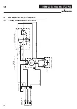
Page 32: ...ight blue brown MOTOR WITH TEMPERATURE SWITCH M 1 Z2 U2 OPERATION CAPACITOR C 25 F 400V black 155 C N L Z1 red green yellow blue black N MOTOR SWITCH 8A b U P1 P2 6 3 light blue blue black 340380 2545...

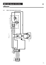
Page 33: ...33 HERO 23D Hero 23 SF 23 Pro GB 4 2 CONNECTION DIAGRAM HERO 23 JAPAN 100V 50 60Hz M 1 Z2 U2 C 100 F 400V 155 C N L Z1 N 8A b U P1 P2 6 3 340380 254518 254519 b...

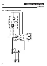
Page 34: ...N POWER CABLE 110V 60Hz TERMINAL STRIP green yellow blue light blue brown MOTOR WITH TEMPERATURE SWITCH M 1 Z2 U2 OPERATION CAPACITOR C 80 F 250V black 155 C N L Z1 red green yellow blue black N MOTOR...

Reviews: