background image

37


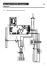
Super Finish 33 PLUS/PRO • Nespray Pro

Earthing and short-circuiting 

After ensuring safe isolation from the supply, the conductors and earthing must be connected together with short-circuit-proof 

earthing and shorting jumpers. With this measure, the upstream overcurrent protective devices trigger and the system is imme-

diately isolated in the event of inadvertent restoration of power. It should be noted that earthing is carried out fi rst, then short-

circuiting. 

Cover or shield any adjacent live parts. 

Often inadmissible approach to adjacent live system parts cannot be easily prevented. In such cases these system parts must be 

protected against accidental contact by permanent and securely fi tted insulating covers.

1.6


CATEGORISATION OF PROTECTION CLASSES 

Legal basis 

In electrical engineering, protection classes enable the categorisation and identifi cation of electrical equipment (for example, 

devices and installation components) in relation to the existing safety measures for protection against electric shock. 

The protection classes are defi ned for all electrical equipment in DIN EN 61140 (VDE 0140-1). 

A distinction is made between four protection classes for electrical equipment. Symbols are provided in order to identify equip-

ment with the relevant protection class. These symbols are defi ned in IEC 60417. The use of safety precautions in the diff erent 

classes of electrical equipment is described in DIN EN 61140 (VDE 0140-1):2007-03, section 7. 

Protection class 0 

There is no special protection against electric shock in addition to the basic insulation. Connection to the protective conductor 

system is not possible. Appliances with this protection class are not permitted in Germany and Austria. This protection class will 

not be included in any international standards in future. There is no symbol for protection class 0. 

Protection class I  

All electrically conductive housing parts of the equipment are connected to the protective conductor system of the fi xed elec-

trical installation, which is at earth potential. Mobile appliances in protection class I have a plug connector with a protective 

conductor contact or an earthing pin plug. These must be executed so that the protective conductor connection is established 

as the fi rst connection on plugging in. It must also be ensured that in the event of damage the protective conductor connection 

is disconnected last. The connecting cable entry into the appliance must be mechanically strain-relieved

Protection class II 

Equipment in protection class II has reinforced or double insulation around live parts, so that no conductive parts can be live 

even in fault conditions. This is also referred to as total insulation. Appliances in protection class II do not have a protective con-

ductor contact. 

Protection class III 

Appliances in protection class III operate with safety extra-low voltage (SELV). 

Safety extra-low voltage means voltages that do not exceed 50 V AC (alternating voltage) or 120 V DC (direct voltage). This vol-

tage must be generated by a safety transformer as per DIN VDE 0570-2-6 or EN 61558-2-6 for a mains-operated appliance.

Safety extra-low voltage taken from batteries or accumulators belongs to protection class III without the need for further mea-

sures. 

GB

Summary of Contents for Nespray Pro

Page 1: ...Service manual with electrical repair instructions for electri cally instructed persons of the J Wagner GmbH 2405146 B 06 2019 Super Finish 33 PLUS Super Finish 33 Pro Nespray Pro...

Page 2: ...y start up 1 Faulty units may not be used 2 Secure a Wagner spray gun with the securing lever at the trigger guard 3 Ensure earthing 4 Check the permissible operating pressure of the high pressure hos...

Page 3: ...Spare parts list trolley_________________________ 27 4 6 Spare parts list suction system rigid ____________ 28 4 7 Spare parts list suction system flexible __________ 28 4 8 Spare parts list hopper 5...

Page 4: ...ires hot sur faces etc in the vicinity 1 4 DANGER OF INJURY FROM THE SPRAY JET Attention danger of injury by injection Never point the spray gun at yourself other persons or animals Never use the spra...

Page 5: ...e unit must be connected to an appropriately grounded safety outlet An electrostatic charging of spray guns and the high pressure hose is discharged through the high pressure hose For this reason the...

Page 6: ...with water 3 8 l min Max temperature of the coating material 43 C Heating of the coating material to 40 C standard Max nozzle size 0 033 inch Zoll 0 84 mm D319 Max viscosity 25 000 mPas Empty weight...

Page 7: ...losed 30 mm wrench on the inlet valve 2 Turn out the inlet valve carefully 6 Clean the valve seat 4 with a cleaning agent and brush ensure that no brush hairs are left behind 7 Clean the seals 5 6 and...

Page 8: ...ressure regulation screw 6 slowly until the pressure gauge shows 250 bar 25 MPa 3625 psi 5 Put pressure regulation knob 5 on the pressure regulati on screw and fully turn it to the right Hold it in th...

Page 9: ...as built up in the hydraulic oil housing 1 Completely unscrew the pressure control valve 1 span ner width 17 mm 2 Remove the front cover 2 by loosening the 5 screws using an Allen key SW 3 The fixed p...

Page 10: ...tart 2404531 see chapter 3 9 Unit runs but makes a strange noise Motor runs without load very silent unit without function Gearwheel inside the gearbox is damaged Replace the gear wheel including the...

Page 11: ...on or fit new switching button Relief valve clogged Clean or replace relief valve Unit loses oil Gasket of front cover de fective Material Unitec 300 possibly problematic Replace front cover gasket K...

Page 12: ...d and there is voltage supply for the motor RED GREEN YELLOW 3 9 SOFT START CONTROLLER UPGRADE SERVICE KIT 2404531 GB 1 Lift the board to loosen screw 1 2 Mount the soft start circuit 2 Attention Plac...

Page 13: ...ght blue blue black LIGHTED SIGNS brown white LED 2388610 2388611 2388612 Z1 U1 red 340380 SOFT START CONTROLLER black black blue L N blue light blue MOTOR WITH TEMPERATURE SWITCH M 1 Z2 U2 OPERATION...

Page 14: ...4 Inlet valve complete SF33 PLUS Inlet valve complete Nespray Pro 5 0341 255 0341 256 Inlet valve housing compl SF33 PLUS Inlet valve housing compl NesprayPro 6 0341 349 Oil cap screw 7 9971 146 O rin...

Page 15: ...13 14 15 16 17 18 19 20 21 22 23 24 25 26 27 28 29 30 31 32 33 34 35 36 37 38 39 40 41 20Nm 70Nm 15Nm 1 Explanation xNm indicates torque 1 seal with Loctite 414 order no 3065559 fill in 1 1 l hydrauli...

Page 16: ...ssure gauge 15 0261 352 Mains cable H07 RNF 3x 1 5mm 6m long 16 2402 675 Cable threaded joint 17 2386 850 Label SF 33 Pro 18 0169 248 Relief valve compl 19 2344 692 Motor gasket 20 2386 858 Label righ...

Page 17: ...6 7 8 9 10 12 5 11 13 15 16 17 14 18 19 20 21 22 23 24 25 26 27 28 30 29 15Nm 70Nm 1 Explanation xNm indicates torque 1 seal with Loctite 414 order no 3065559 fill in 1 0 l hydraulic oil order 21061...

Page 18: ...control knob assy 1 19 2385357 Label pressure control valve 1 20 2405099 Pressure control valve SF 33 assy 1 21 3051678 O ring 9x3 1 22 2396020 Seal Cu 1 23 2370116 Sleeve rubber 1 24 2367512 Liner D...

Page 19: ...17 18 19 20 21 22 23 24 90Nm 25 26 27 Tighten carefully cross wise to avoid tilting pos 6 do not damage O rings Explanation xNm indicates torque 1 seal with UHU Plus 2K order no 28 70Nm 1 29 Tighten c...

Page 20: ...82 Lens head screw M4x10 4 7 9920130 Washer 4 8 2383936 Multi function switch assy SF 33 PLUS 1 9 2334205 Cylinder head screw M4x40 2 10 9971197 O ring 13x1 5 1 11 2384478 Control knob 1 12 9920207 Wa...

Page 21: ...21 Super Finish 33 PLUS PRO Nespray Pro 2 5Nm 1 3 4 5 6 7 8 9 10 11 12 13 14 15 Version SF 33 PRO 4 5 3 Explanation xNm indicates torque GB...

Page 22: ...22 Super Finish 33 PLUS PRO Nespray Pro 1 2 3 4 5 6 7 8 10 11 12 13 15Nm 15Nm Legende xNm gibt Drehmoment an 5Nm 9 GB...

Page 23: ...abel SF 33 Pro Rating label Nespray Pro 1 1 1 9 2368785 O ring 144x3 1 10 2315382 Oval head screw M4x10 4 11 2334046 Connecting plate 2 12 9900330 Cylinder head screw M10x20 4 13 2367479 Electric moto...

Page 24: ...6464 Locking ring 1 4 9970532 Shaft seal 1 5 2333811 Eccentric shaft 1 6 9960151 Groove ball bearing 1 7 9922518 Locking ring 1 8 9960431 Roller bearing 1 9 9922506 Locking ring 1 10 9960432 Cylinder...

Page 25: ...all bearing 8 9 2367482 Planet carrier 4 fold 1 Service kits 2400486 Small parts gearbox SF33 consisting of item 1 3 4 5 2400485 Planetary wheel assy set of 4 consisting of item 6 7 8 Order number for...

Page 26: ...ng 4 0097 306 Hollow screw 5 0097 304 Seal ring 6 9970 110 Seal ring 7 9974 027 O ring 30x2 PTFE 8 9971 401 O ring 16x2 PTFE 9 0508 749 Bearing spring 10 0508 603 Bearing ring 11 0508 748 0508 450 050...

Page 27: ...hex socket 4 2391 797 Mini screen 5 2384 267 Hexagon nut M10x1 6 9913 011 Hexagon nut 7 9920 106 Washer A 10 5 8 0348 349 Wheel 9 9994 902 Wheel cap 10 2384 275 Damping plate 11 9900 247 Hexagon scre...

Page 28: ...ORDER NO DESIGNATION 1 2370 310 Suction system assy incl pos 2 3 2 0253 244 Filter mesh width 1 2 mm 3 0253 211 Return tube ITEM ORDER NO DESIGNATION 0034 630 Suction system assy 1 0034 607 Suction h...

Page 29: ...0003 756 Filter disk mesh width 0 8 mm Optional Filter disk mesh width 0 4 mm 4 0340 904 Hopper 5 0340 908 Return ube ITEM ORDER NO DESIGNATION 0341 266 Hopper 20 litres assy 1 0097 269 Hopper without...

Page 30: ...4 10 HOSE REEL The hose reel is suitable for max 30 m hose 1 4 NPSM Single hoses can be connected with the adapter 34038 SF 33 PLUS 1 2 3 SF 33 PRO 1 2 3 Screw the hose reel 1 with holder 2 onto the...

Page 31: ...31 Super Finish 33 PLUS PRO Nespray Pro GB...

Page 32: ...244 Terminal strip 6 way 32 2311 150 Swivel joint assy 33 9921 902 Retaining washer D6 DIN 6799 34 2311 153 Threaded rod POS ORTDER NO DESIGNATION 35 2311 148 Tube assy 36 9901 319 Threaded insert 37...

Page 33: ...Pro Spare parts diagram Heating hose drum 39 40 41 42 43 44 45 46 47 48 49 50 51 52 53 54 55 56 57 58 59 60 61 62 63 64 65 1 2 3 4 5 6 7 8 9 10 11 12 13 14 15 16 17 18 19 20 21 22 23 24 25 26 27 28 2...

Page 34: ...9 2311 136 Sensor screw connection 10 9900 392 Socket head cap screw M4x6 DIN 912 4 11 9922 101 External tooth lock washer A4 3 DIN6797 12 2308 061 NTC Temperature sensor 13 2312 115 Heating wire Spa...

Page 35: ...ntial hazards and special features The work instructions must include safe and correct replace ment of a connecting cable for example 1 2 SKILLED ELECTRICIAN FOR DEFINED TASKS In order to autonomously...

Page 36: ...e cables must be disconnected at all poles at the place of work before starting work This can be done by means of main switches expert removal of fuses disconnection of plug connectors etc Protecting...

Page 37: ...ic shock in addition to the basic insulation Connection to the protective conductor system is not possible Appliances with this protection class are not permitted in Germany and Austria This protectio...

Page 38: ...n Explanation L1 External conductor L2 External conductor L3 External conductor N Neutral conductor PE Protective conductor 3 Threephase AC voltage 1 8 EXPLANATION OF ELECTRICAL TERMS Rated current Th...

Page 39: ...nductor is an earthed conductor which performs the function of protective conductor and neutral conductor simulta neously Active part of an electrical system An active part is a live part of an electr...

Page 40: ...e wire is defective 7 The defective component must be made inoperative in order to prevent further use 2 2 FUNCTIONAL TEST OF THE CAPACITOR 1 Ensure safe isolation from the supply before commencing wo...

Page 41: ...be used to check the electrical functionality If a multimeter is used it should be set to V or VAC 5 Now check the voltage present between L1 and N If this is 230 V AC then the voltage between L1 and...

Page 42: ...first of all Note down the connection plan 4 Measure all cables to the housing if a continuity is found then the motor has an earth fault and is defective 5 Measurement of the individual windings is n...

Page 43: ...ordance with BGV A3 must be carried out in order to ensure electrical safety and functionality See chapter 1 4 3 3 REPLACING THE CAPACITOR 1 Ensure safe isolation from the supply before commencing wor...

Page 44: ...ections from the motor protecting switch 4 The motor protecting switch can now be removed 5 Now install the new motor protecting switch and restore the electrical connection 6 After completing the rep...

Page 45: ...act pin assignment 3 Now replace the motor 4 Observe the pin assignment noted in point 2 when connecting the individual wires Also ensure secure contact when con necting the wires 5 After completing t...

Page 46: ...TERMINAL STRIP blue brown green yellow light blue MOTOR WITH TEMPERATURE SWITCH M 1 Z2 U2 black OPERATION CAPACITOR C 40 F 400V black MICRO SWITCH grey blue black 155 C COM NC NO N L green yellow gre...

Page 47: ...w blue light blue brown MOTOR WITH TEMPERATURE SWITCH M 1 U2 Z2 black OPERATION CAPACITOR C 40 F 400V black MICRO SWITCH grey blue black 155 C COM NC NO N L green yellow green yellow blue light blue b...

Page 48: ...SION POWER CABLE 230V 50Hz TERMINAL STRIP blue brown green yellow light blue MOTOR WITH TEMPERATURE SWITCH M 1 Z2 U2 OPERATION CAPACITOR C 35 F 400V black black 155 C N L Z1 U1 red green yellow blue b...

Page 49: ...ER POWER CABLE 230V 50Hz TERMINAL STRIP green yellow blue light blue brown MOTOR WITH TEMPERATURE SWITCH M 1 Z2 U2 OPERATION CAPACITOR C 40 F 400V black black 155 C N L Z1 U1 red gr n gelb blue black...

Page 50: ...SWITCH M 1 U2 Z2 black OPERATION CAPACITOR C 40 F 400V MICRO SWITCH grey blue black 155 C COM NC NO N L green yellow green yellow blue Z1 U1 red light blue blue black LIGHTED SIGNS brown white LED POW...

Page 51: ...IZN HEIZREGLER 20 C 60 C FRONTDECKEL TROMMEL GEH USE GR N GELB GR N GELB SCHWARZ BLAU KLEMME NETZSTECKER 230V 50 Hz GR N GELB BLAU BRAUN GR N GELB BLAU SCHWARZ SCHLEIFRINGK RPER HEIZDRAHTSCHLAUFE TEMP...

Reviews: