8
Super Finish 33 PLUS/PRO • Nespray Pro
3.4
PRESSURE CONTROL VALVE
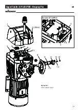
To remove the pump, move it to an upright
position. Open the oil lock screw (A) to re-
lease any excess pressure that has built up in
the hydraulic oil housing.
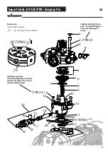
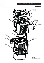
1. Insert regulator (10) and tighten it (approx. 15 Nm).
2. Mount stop sleeve (4) and clamp (3).
3. Turn pressure regulation screw (6) to the left until the
spring snaps (pressure = 0).
4. Attach suction system or hopper.
Test medium: water
5. Mount a pressure gauge (0 – 400 bar), an original pressure
hose from Wagner and a high pressure airless gun.
SETTING THE MAXIMUN OPERATING PRESSURE
(CLOSING PRESSURE)
1. Lock the spray gun.
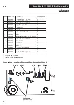
2. Set multifunction switch to
, switch on the machine
and let it run for 2-3 minutes for ventilation. Turn the pres-
sure regulation screw (6) slowly until the machine starts to
suck in water.
3. Set multifunction switch to
and trigger spray gun for
ventilating high pressure hose and spray gun. Lock the
spray gun .
4. Turn the pressure regulation screw (6) slowly until the
pressure gauge shows 250 bar (25 MPa, 3625 psi).
5. Put pressure regulation knob (5) on the pressure regulati-
on screw and fully turn it to the right. Hold it in this positi-
on and pre-assemble the pin (7) with a 2.5 mm hexagonal
wrench, loosen and tighten again with 1 Nm..
6. Turn pressure regulation knob to the left.
7. Release pressure by pressing the trigger of the the spray
gun.
8. Control setting while the gun is locked again (turn pressu-
re control knob to the right again).
9. Seal pin with red sealing wax (1 litre, order no. 9992512).
10. Set multifunction switch to
.
11. Machine is ready for operation!
3.3
OUTLET VALVE
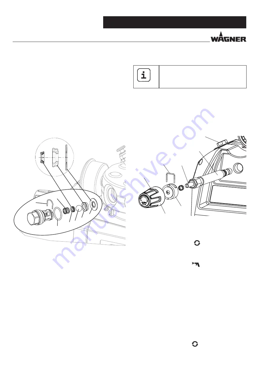
1. Use a 22 mm wrench to screw the outlet valve from the
paint section.
2. Carefully pull of the clasp (1) using the enclosed screw-
driver. The compression spring (2) presses ball (4) and
valve seat (5) out.
3. Clean or replace the components.
4. Check the O-ring (7) for damage.
5. Check the installation position when mounting the spring
support ring (3) (clipped onto spring (2)), outlet valve seat
(5) and seal (6), refer to figure.
The torque for fitting the outlet valve is 50 Nm.
1
2
7 3
4 5
6
3
4
5
6
7
10 (15 Nm)
A
GB


