17
PEA-C4-HiCoat
G
X
A
A
C
D
B
P_01612
H
F
G
E
X
OPERATING MANUAL
VERSION 05/2012
ORDER NUMBER DOC 390829
5
DESCRIPTION
5.1
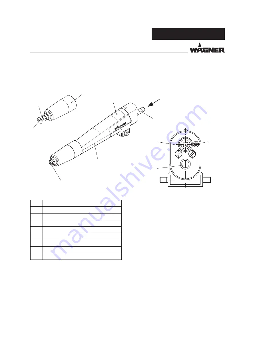
DESIGN OF SPRAY GUN
Description
A
Flat spray nozzle (defl ector cone)
B
Electrode
C
Cap nut
D
Gun body
E
Electrical connection
F
Atomizing air connection
G
Powder hose connection
H
Type plate
5.2
FUNCTIONING OF THE SPRAY GUN
The spray gun is switched on and off via the superordinated control unit.
At the same time the air supply and high-voltage are activated.
The distance of the installed spray guns to each other must be at least 300 mm; 11.81 inches
for functional reasons.
The gun control cabinet must be switched off in order to lock the spray gun!
If changing from the fl at spray nozzle to the defl ector cone, the depth control must be
adjusted.

