background image

48

PEA-C4-HiCoat

OPERATING MANUAL

VERSION 05/2012

ORDER NUMBER DOC 390829

S

e

c

tion

T

y

pe of Inspec

tion

Requir

emen

ts

Inspec

tion 

by

T

y

pe of Inspec

tion

Inspec

tion In

ter

v

al

1E

ff 

ec

tiv

eness of t

echnical 

v

e

ntilation check

Eff

 ec

tiv

eness of t

echnical 

v

e

ntilation check

TP/CP

ME

e

.g

. measur

ements of air fl

 ow


speed / air quantities

,

check

ing of the diff

 er

ential 

pr

essur

e indicat

or ac

co

rding 

to

 the cabin manufac

tur

er's 

instruc

tions

.

co

ntinuously

ac

co

rding t

o

 the cabin 

manufac

tur

er's instruc

tions

2

Int

erlock bet

w

een t

echnical 

v

e

ntilation and high-v

oltage

compr

essed air and c

o

ating 

mat

e

rial supply

T

he t

echnical v

e

ntilation should 

be int

e

rlocked such that the high-

v

oltage cannot be swit

ched on 

while the t

echnical v

e

ntilation is 

not w

o

rk

ing eff

 ec

tiv

ely

.

CP

FI

Test whether the sy

st

em is saf

ely 

st

opped and the mat

e

rial supply

supply air and high-v

oltage 

ar

e swit

ched off

  when the 

v

e

ntilation is shut do

wn.

annually

3

P

ro

te

c

tion against ig

nition of 

fl 

ammable cleaning agents

If

 fl

 ammable cleaning fl

 uids 

ar

used

, all par

ts carr

ying high-

v

oltage must be dischar

ged t

o

 a 

dischar

ge ener

gy of less than 0,24 

mJ

, onc

e the high-v

oltage has 

been swit

ched off

 , bef

or

e they can 

be r

eached

.

CP

ME/FI

F

unc

tion t

est of the r

esidual 

ener

gy monit

oring equipment 

ac

co

rding t

o

 the manufac

tur

er's 

instruc

tions

.

ac

co

rding t

o

 the 

manufac

tur

er's instruc

tions

Ke

y

:

M

A

 = M

anufac

tur

er

EM = Emplo

y

e

r

CP = C

apable person

FSE = F

ir

e

 saf

et

y eng

ineer

EL

C = Elec

trician

TP = 

T

rained person

FI = F

unc

tion inspec

tion

ME = M

easur

ement

SI = Standar

d inspec

tion

VI = 

V

isual inspec

tion

CI = C

o

ntinuous inspec

tion

TI = 

Technical inspec

tion

9.1 

OVERVIEW OF INSPECTIONS

Summary of Contents for PEA-C4-HiCoat FM

Page 1: ...0102 II 2 D EEx 2mJ 85 C P_01610 Automatic Powder Spray Gun PEA C4 HiCoat Version 05 2012 Translation of the Original Operating Manual...

Page 2: ......

Page 3: ...d Operating Equipment 12 4 1 2 Personnel Qualifications 12 4 1 3 A safe Work Environment 12 4 2 Safety Instructions for Staff 13 4 2 1 Safe Handling of WAGNER Powder Spray Devices 13 4 2 2 Grounding t...

Page 4: ...nce Procedures 35 8 2 4 Replacing the Spray Gun 36 8 3 Cleaning the Spray Gun and Dismantling the Flat Spray Nozzle 37 8 4 Replacing the Protective Wedge 38 8 5 Fitting the Round Spray Nozzle 40 8 6 F...

Page 5: ...at Corona Automatic Gun 59 13 3 Electrode Holder C4 R with Nozzles 60 13 4 Angle Adapter WA90 C4 61 13 5 Angle Adapter WA60 C4 62 13 6 Angle Adapter WA30 C4 63 14 DECLARATION OF WARRANTY AND CONFORMIT...

Page 6: ...er Non observance may result in death or serious injury Caution a possibly hazardous situation Non observance may result in minor injury Note provides information about particular characteristics and...

Page 7: ...tions 1 3 COPYRIGHT J Wagner AG Tel 41 0 71 757 2211 Industriestrasse 22 Fax 41 0 71 757 2222 Postfach 663 www wagner group com CH 9450 Altst tten rep ch wagner group ch 1 4 CONTACT DETAILS The operat...

Page 8: ...sed in potentially explosive atmospheres zone 22 See explosion protection identification Chap 3 1 2 4 SAFETY PARAMETERS The powder spray gun is only suited to the application of powder paint J Wagner...

Page 9: ...sidual risks are risks which cannot be excluded even in the event of correct use If necessary warning and prohibition signs at the relevant points of risk indicate residual risks Residual Risk Source...

Page 10: ...1 EPG DP 5 EPG Prima EPG SL 5 EPG 2008 EPG 2025 Digifl EPG 2007 Gun type PEA C4 HiCoat Manufacturer J Wagner AG CH 9450 Altst tten II 2 D EEx 2mJ 85 C CE Communaut s Europ ennes 0102 Number of appoint...

Page 11: ...he following indications The equipment may only be operated by trained staff Before starting cleaning the spray gun or carrying out any other work in the spray area the high voltage must be shut down...

Page 12: ...tions Ensure that the device is operated and repaired only by trained persons The floor in the working area must be electrostatically conductive measurements according to EN 1081 and EN 61340 4 1 The...

Page 13: ...fore all work on the device in the event of work interruptions and functional faults Switch off the energy compressed air supply Lock spray guns to prevent them actuating Relieve pressure on spray gun...

Page 14: ...rgy of less than 0 24 mJ before they can be reached Most flammable solvents have a firing power of around 24 mJ or 60 nC The cleaning agent s flash point must be at least 15 K above the ambient temper...

Page 15: ...near the grounded work piece This luminous discharge does not involve any firing power and has no effect on system handling When the electrode approaches the work piece the control unit automatically...

Page 16: ...onditions is not fulfilled the high voltage is switched off immediately After the fault has been eliminated and acknowledged the enabling mechanism can be selected again An automatic switch on is prev...

Page 17: ...hose connection H Type plate 5 2 FUNCTIONING OF THE SPRAY GUN The spray gun is switched on and off via the superordinated control unit At the same time the air supply and high voltage are activated Th...

Page 18: ...3 MPa 43 51 psi Powder output quantity max 450 g min max 0 99 lbs min Ambient conditions Operating temperature range 5 45 C 41 113 F Relative humidity 75 5 3 TECHNICAL DATA Outgoing air containing oil...

Page 19: ...X OPERATING MANUAL VERSION 05 2012 ORDER NUMBER DOC 390829 5 3 1 DIMENSIONS Measurement mm inch A 395 133 66 B 30 1 18 C 310 12 20 D 76 2 99 E 82 3 23 Measurement for installation dimension C calcula...

Page 20: ...390893 Declaration of conformity 1 390822 Operating manual German 1 see chap 1 1 Operating manual in local language 5 5 SCOPE OF DELIVERY 5 4 PERMITTED ACCESSORIES Only the accessories listed in this...

Page 21: ...CONDITIONS The air temperature at the installation site must be between 5 45 C 41 113 F Depending on the powder paint used the maximum permissible ambient temperature for reliable operation can be si...

Page 22: ...cloud high penetration capability for profile parts high stability F4 Wide flat spray nozzle for high powder application slow powder cloud 200 Total air 4 5 Nm h 150 400 good atomization specially for...

Page 23: ...lat spray nozzle for high powder application slow powder cloud 200 Total air 4 5 Nm h 150 400 good atomization specially for extensive work pieces 1 Nozzles are labeled on the back Deflector Cone Appl...

Page 24: ...ical cable to the control unit 4 Connect the powder feed hose to the spray gun and to the powder injector 5 Connect the atomizing air hose to the spray gun and to the control unit 6 5 MOUNTING THE SPR...

Page 25: ...and suspension by the customer in accordance with the operating manual or the manufacturer s information Grounding of all conductive parts of the system The resistance to ground of every work piece s...

Page 26: ...ly use mains cables with grounding strand 2 Connect grounding cable with booth and system ground 3 Connect grounding cable to an uncoated metal part of the booth 4 Remove all paint from hooks and othe...

Page 27: ...st be familiar with the provisions of European standard DIN EN 50177 WARNING Incorrect operation Risk of injury and damage to the device If contact with powder materials or cleaning agents causes skin...

Page 28: ...r the automatic purging mode please proceed as follows Procedure 1 The atomization air has to remain open to prevent powder from penetrating into the atomization air channel and the cascade compartmen...

Page 29: ...wder feed Note To minimize the wear on the wearing parts the total feed air and dosage air should be under 5 Nm h The atomizing air should be adjusted for the flat spray nozzle to 0 1 Nm h round spray...

Page 30: ...system Disconnect the powder hose from the spray gun Blow through the spray gun using the air gun and thus remove any powder residues Switch off the system and secure against unauthorized reactivatio...

Page 31: ...on to achieve a smoother coating the protective wedge is now in the vertical position It is possible to change this position as needed for special applications On the nozzle body and electrode holders...

Page 32: ...es Danger to life and equipment damage Before starting cleaning or other manual work the high voltage mustbeshutdownandlockedtopreventitfrombeingswitched back on Use only electrically conductive conta...

Page 33: ...must be adhered to for all cleaning work 8 1 3 CLEANING PROCEDURES Incorrect maintenance Risk of injury and damage to the device If contact with powder materials or cleaning agents causes skin irritat...

Page 34: ...condition 8 2 1 MAINTENANCE STAFF 8 2 2 SAFETY INSTRUCTIONS Incorrect maintenance repair Risk of injury and damage to the device Have repairs and part replacements be carried out by specially trained...

Page 35: ...t be adhered to for all maintenance work 8 2 3 MAINTENANCE PROCEDURES Incorrect maintenance Risk of injury and damage to the device If contact with powder materials or cleaning agents causes skin irri...

Page 36: ...aced Procedure 1 Switch of the system or the high voltage generation 2 Disconnect the electrical cable 1 from the gun 2 3 Disconnect the hoses for powder feed 3 and atomizing air 4 from the spray gun...

Page 37: ...er 3 from gun housing 5 Note Do not damage the electrode holder when pulling out and inserting 4 Remove powder residues from the parts removed and from the spray gun Note Never place the spray gun or...

Page 38: ...1 Guide wedge tool 1 into electrode holder 3 up to stop 2 Pull the protective wedge 2 out of the electrode holder 3 using the wedge tool 1 3 Press manually without tool the protective wedge 2 sideways...

Page 39: ...e tool in as far as the mark X rotate the wedge tool a little until it can be pushed up to the mark The mark X must be flush with the end Y of the electrode holder 4 The protective wedge is now correc...

Page 40: ...Note Do not damage the electrode holder when pulling out and inserting 4 Remove powder residues from the parts removed and from the spray gun 5 After long periods of operation or having replaced the...

Page 41: ...holder 6 into the spray gun housing 5 6 Slide the deflector cone sleeve 7 onto the electrode holder 6 7 Align the marks X and Y 8 Fasten cap nut 1 9 Slide the deflector cone 8 over the deflector cone...

Page 42: ...apter WA90 C4 WA 60 C4 or WA30 C4 is necessary to perform the change as listed in chapter 12 Accessories Note A flat spray nozzle as well as a round spray nozzle can be fitted to the angle adapter 8 6...

Page 43: ...4 2 Push angle adapter 5 onto the gun body and screw slightly threaded sleeve 6 3 Swivel angle adapter 5 in the desired position and then tighten well threaded sleeve 6 8 6 3 REPLACEMENT OF THE WEARI...

Page 44: ...mponents thoroughly and remove any powder residues 10 Install nozzle insert 7 as shown in loupeY1 and Y2 in such a way that the pin B1 is guided into the hole A1 11 Install connecting element 11 withi...

Page 45: ...from the spray gun housing B 3 Screw the new nut C for the Corona Star D onto the spray gun housing and fasten in place 4 Fasten the cable guide onto the cover plate F by using the screw E 5 Slide the...

Page 46: ...ion of fitting shown is example only 4 Fix the connection cable 3 on the spray gun housing Note Check whether the grounding is assured 5 The spray gun is ready for use again Note Put stopper back into...

Page 47: ...IN ACCORDANCE WITH DIN EN 50177 2010 04 If the system is used for electrostatic coating with flammable coating powders testing should be undertaken in accordance with DIN EN 50177 2010 04 as perTable...

Page 48: ...hnical ventilation is not working eff ectively CP FI Test whether the system is safely stopped and the material supply supply air and high voltage are switched off when the ventilation is shut down an...

Page 49: ...sistance to ground of work piece s locating point The resistance to ground of every work piece s locating point must not exceed 1 megaohm measurement voltage must be 500 or 1000 V The design of the wo...

Page 50: ...e device Before starting disassembly Switch off the energy compressed air supply Ensure that all system components are grounded Secure system against being switched back on without authorization Obser...

Page 51: ...system components are grounded Secure the unit against being switched back on without authorization Observe the operating and service instructions when carrying out all work DANGER Incorrect maintena...

Page 52: ...ay Insufficient or no grounding See chapter 6 7 Grounding Powder outlet uneven or inadequate Contamination Blow through parts carrying powder Powder sintering Clean parts carrying powder Feed device c...

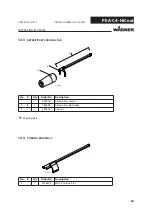
Page 53: ...R DOC 390829 12ACCESSORIES 12 1 FLAT SPRAY NOZZLES Order No Description 390324 F1 flat spray nozzle 390325 F2 flat spray nozzle 390326 F3 flat spray nozzle 2311889 F4 flat spray nozzle 390331 HPO 1 wi...

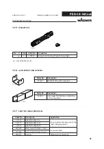
Page 54: ...2012 ORDER NUMBER DOC 390829 No K Qty Order No Description 1 1 390918 Corona Star compl 2 1 260296 Corona Star electrode 3 1 390319 Cap nut Wearing part 12 3 RETROFIT SET CORONA STAR 12 4 CORONA STAR...

Page 55: ...on 351347 Bracket for fixing the spray gun Order No Description 260215 Gun support for fixation on mounting on the reciprocator 12 7 ELECTRIC CABLES AND HOSES Order No Description Application 351216 E...

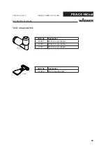
Page 56: ...OPERATING MANUAL VERSION 05 2012 ORDER NUMBER DOC 390829 12 8 ANGLE ADAPTER Order No Description 390927 WA30 C4 angle adapter 390930 WA60 C4 angle adapter 390931 WA90 C4 angle adapter Order No Descri...

Page 57: ...rder No Description 390940 Powder measuring bag compl For measuring powder quantities for the C4 gun generation The powder measuring bag is slid onto the nozzle Risk of explosion due to electrostatic...

Page 58: ...arts lists Address for the invoice Address for delivery Name of the person to be contacted in the event of any queries Type of delivery normal mail express delivery air freight courier etc Wearing par...

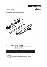
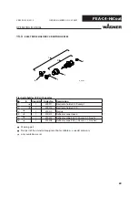
Page 59: ...No K Quantity Order No Description 1 1 390004 PEA C4 HiCoat Corona automatic gun 2 1 390311 Cap nut 3 1 390324 Flat spray nozzle F1 4 1 390915 Electrode holder 5 1 390310 Wedge 6 1 390911 Powder tube...

Page 60: ...1 1 390917 Electrode holder C4 R compl 2 1 390916 Electrode holder C4 R 3 1 390310 Wedge 4 1 390313 Deflector cone sleeve 5 1 390207 Deflector cone R20 20 mm 0 79 inch 6 1 390208 Deflector cone R28 28...

Page 61: ...gle adapter WA90 C4 2 1 390947 Cap nut WA C4 ET 3 1 390933 Nozzle insert WA90 C4 ET 4 1 390942 Angle adapter WA90 C4 ET 5 1 390932 Connecting element WA C4 ET 6 1 390946 Locking sleeve WA C4 ET 7 1 39...

Page 62: ...gle adapter WA60 C4 2 1 390947 Cap nut WA C4 ET 3 1 390934 Nozzle insert WA60 C4 ET 4 1 390943 Angle adapter WA60 C4 ET 5 1 390932 Connecting element WA C4 ET 6 1 390946 Locking sleeve WA C4 ET 7 1 39...

Page 63: ...gle adapter WA30 C4 2 1 390947 Cap nut WA C4 ET 3 1 390935 Nozzle insert WA30 C4 ET 4 1 390944 Angle adapter WA30 C4 ET 5 1 390932 Connecting element WA C4 ET 6 1 390946 Locking sleeve WA C4 ET 7 1 39...

Page 64: ...terial costs will be borne by us except where these costs are increased due to the subsequent shipment of the unit to a location other than the address of the purchaser We do not provide warranty for...

Page 65: ...04 108 EC EMC Directive 2002 95 EC RoHs Directive 2002 96 EC WEEE Directive Applied standards in particular DIN EN 50177 2010 DIN EN 50050 2007 DIN EN 60079 0 2010 DIN EN 1127 2008 DIN EN 1953 2010 DI...

Page 66: ...66 PEA C4 HiCoat OPERATING MANUAL VERSION 05 2012 ORDER NUMBER DOC 390829 14 4 EC TYPE EXAMINATION CERTIFICATE...

Page 67: ...67 PEA C4 HiCoat OPERATING MANUAL VERSION 05 2012 ORDER NUMBER DOC 390829...

Page 68: ...68 PEA C4 HiCoat OPERATING MANUAL VERSION 05 2012 ORDER NUMBER DOC 390829...

Page 69: ...69 PEA C4 HiCoat OPERATING MANUAL VERSION 05 2012 ORDER NUMBER DOC 390829...

Page 70: ...rance fr Netherlands WAGNER Systemen Nederland Proostwetering 105 C NL 3543 AC Utrecht Phone 31 30 2410 688 Fax 31 30 2410 765 E mail info wagnersystemen nl Italy WAGNER Itep S p A Via Santa Veccia 10...

Page 71: ......

Page 72: ...tfach 1120 D 88677 Markdorf Tel 49 0 7544 5050 Fax 49 0 7544 505200 E mail service standard wagner group com Switzerland J Wagner AG Industriestrasse 22 Postfach 663 CH 9450 Altst tten Tel 41 0 71 757...

Reviews: