background image


0102

P_01090

II 2 D EEx 2mJ 85°C

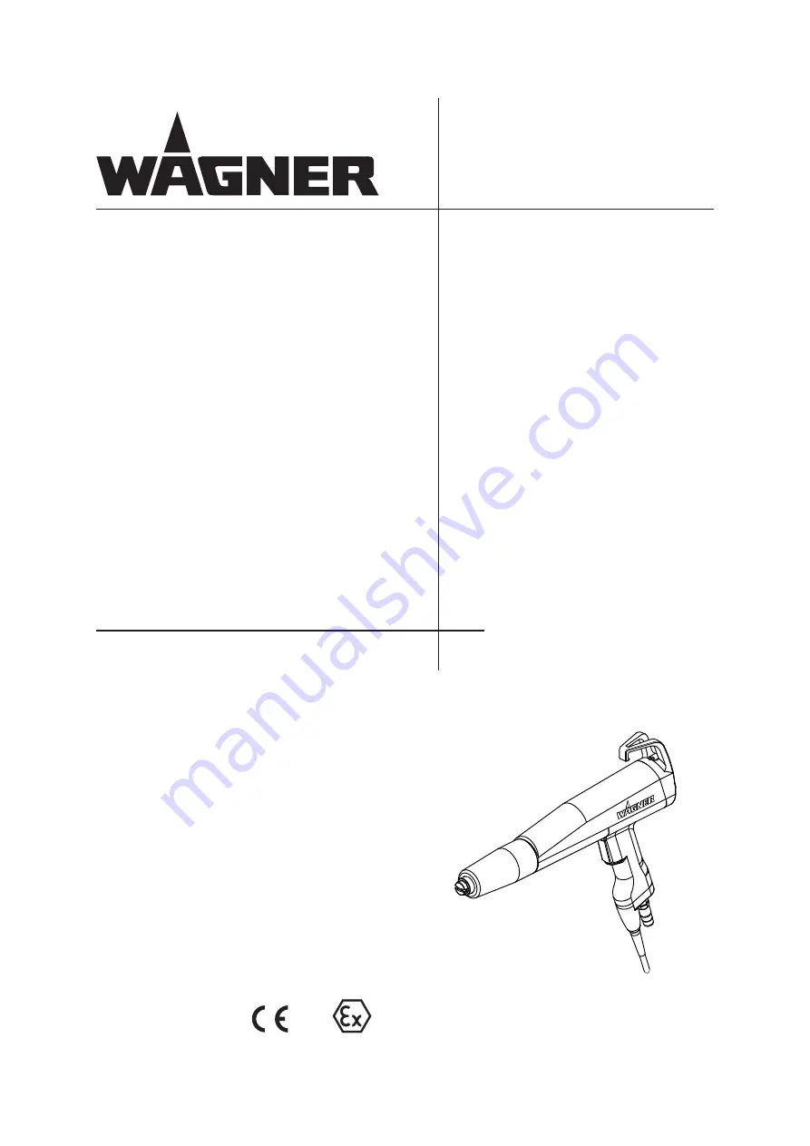
Powder Coating Guns

PEM-C4-Ergo

Version 02 / 2009

Translation of the original 
Operating manual

Summary of Contents for PEM-C4-Ergo

Page 1: ...0102 P_01090 II 2 D EEx 2mJ 85 C Powder Coating Guns PEM C4 Ergo Version 02 2009 Translation of the original Operating manual ...

Page 2: ......

Page 3: ...dentification 8 2 5 Note on harmless discharges 9 3 WARRANTY AND DECLARATION OF CONFORMITY 10 3 1 Important notes on product liability 10 3 2 Warranty 10 3 3 CE conformity 11 4 DESCRIPTION 12 4 1 Fields of application using in accordance with the instructions 12 4 1 1 Processing materials 12 4 2 Scope of delivery 12 4 3 Technical data 13 4 3 1 Dimensions 14 4 4 Functional description 15 4 4 1 Desi...

Page 4: ... 7 4 Fitting the round spray nozzle 29 7 5 Mounting the Corona Star 31 7 6 Mounting the C4 gun extension 32 7 7 Mounting the C4 VL300 500 S gun extension 34 7 8 Replacing the protective wedge in the spray gun extension 36 7 9 Replacing the centring pins 40 7 10 Disposal 41 8 TROUBLE SHOOTING AND RECTIFICATION 42 9 ACCESSORY 43 9 1 Fan spray nozzles 43 9 2 Deflector cone 43 9 3 C4 gun extension Cor...

Page 5: ...s line warns of the hazard Possible consequences of failing to observe the warning instruc tions The signal word points out the hazard level The measures for preventing the hazard and its consequences SIHI_0103_GB WARNING This line warns of the hazard Possible consequences of failing to observe the warning instruc tions The signal word points out the hazard level The measures for preventing the ha...

Page 6: ...d on active parts Secure the control unit against being switched back on without authorisation Inform staff about planned work Observe electrical safety regulations ª Ensure that the floor of the working area is anti static measurement in accordance with EN 1081 ª Ensure that all persons within the working area wear anti static shoes ª Ensure that gloves that are being worn are made of conductive m...

Page 7: ...ecure the powder spray gun against actuation Relieve the pressure from the powder spray gun and unit By functional faults Identify and correct the problem proceed as described in chap Trouble shooting The electrostatic charge may in certain cases give rise to electrostatic charges on the device These can involve with unloading transmitting or flame formation ª Ensure that the device is grounded bef...

Page 8: ...the prescribed safety measures in particular the wearing of safety glasses and safety clothing as well as the use of protective hand cream Use dust masks or breathing apparatus To ensure sufficient protection of health and the environment only operate the device in a powder booth or at a spray wall with activated ventilation exhaust air 2 4 1 USING IN ACCORDANCE WITH THE INSTRUCTIONS 2 4 2 EXPLOSIO...

Page 9: ... grounded workpiece This luminous discharge does not involve any ignition energy and has no effect on the usage of the plant When the electrode approaches the workpiece the control unit automatically reduces the high voltage to a safe value If you touch plastic parts of the spray gun with the finger harmless discharges may occur due to the high voltage field around the spray gun so called brush di...

Page 10: ... than the address of the purchaser This warranty does not cover damage caused by Unsuitable or improper use faulty installation or commissioning by the purchaser or a third party normal wear negligent handling defective maintenance unsuitable coating products substitute materials and the action of chemical electrochemical or electrical agents except when the damage is attributable to us This warra...

Page 11: ...t 94 9 EG Atex directive 2002 95 EG RoHs directive 2002 96 EG WEEE directive Applied standards in particular DIN EN 1127 1 2008 DIN EN 50050 2007 DIN EN 50053 2 1990 DIN EN 61241 0 2007 DIN EN 61241 1 2005 DIN EN 61241 14 2005 DIN EN 60529 2000 BGI 764 Marking CE Certificate of Conformity The certificate is enclosed with this product The certificate of conformity can be reordered from your WAGNER re...

Page 12: ...Quantity Order No Description 1 2305069 PEM C4 Ergo manual gun The standard equipment includes 1 2304981 Declaration of conformity 1 2305053 Operating manual German 1 see chapter 1 1 Operating manual in the local language 4 2 SCOPE OF DELIVERY SIHI_05056_ENG WARNING Incorrect use of the spray gun Risk of injury and damage to the equipment Only connect original Wagner devices to the PEM C4 Ergo spr...

Page 13: ...3 MPa 43 51 psi Powder output quantity max 450 g min max 0 99 lbs min Operating temperature range 5 45 C 41 113 F 4 3 TECHNICAL DATA SIHI_05034_ENG WARNING Outgoing air containing oil Risk of poisoning if inhaled Provide water free and oil free compressed air quality standard 3 5 2 as per ISO 8573 1 3 5 2 5 μm 7 C 44 6 F 5mg m Ambient conditions If low temperature powders are used the ambient temp...

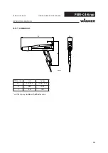
Page 14: ...PEM C4 Ergo P_01092 A B C OPERATING MANUAL VERSION 02 2009 ORDER NUMBER DOC2305054 4 3 1 DIMENSIONS Dimension mm inches A 355 385 13 98 15 16 B 265 10 43 C 46 1 81 with fan spray nozzle with deflector cone ...

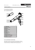
Page 15: ... gun body D Trigger E Outer nut F Deflector cone G Electrode H Fan spray nozzle I Atomizing air connection K Powder hose connection L Electrical connection 4 4 2 FUNCTIONING OF THE SPRAY GUN High voltage is activated in the manual gun when the trigger is actuated The powder supply and air supply to the gun are activated at the same time The control unit must be switched off in order to lock the sp...

Page 16: ...val powder cloud Size of the powder cloud is dependent on the deflector cone diameter Nozzle Application Distance to workpiece mm Powder output g min F1 Universal application slow powder cloud Deep and complex shapes Extensive workpieces 120 300 50 250 F2 Targeted application dense powder cloud High penetration Wide coating range 120 400 30 200 WARNING Incorrect installation operation Risk of inju...

Page 17: ...eces 120 300 30 150 HPO 1 Wide fan spray nozzle for high powder application slow powder cloud Good dispersion Special for extensive workpieces 200 total air 4 5 Nm h 150 400 1 Nozzles are labeled on the back Deflector cone Application Distance to workpiece mm Powder output g min R20 20 mm Small even workpieces 100 300 30 250 R28 28 mm Medium sized even workpieces Lateral application with Z axis 10...

Page 18: ...ontrol unit it is possible to automatically blow out or purge the spray gun each time prior to switch off Atomizing air from the control unit Powder feed from the powder injector to the electrical connection at the control unit SIHI_05057_ENG WARNING Unintentional putting into operation Risk of injury Before all work on the unit in the event of work interruptions and functional faults Switch off t...

Page 19: ...ectric charging of the workpiece Very bad wrap around Uneven coating Backspraying to the spray gun i e contamination Sparks between workpiece and conveyor hooks hangers can occur if hooks or other hanger parts are not completely cleaned These sparks can cause heavy radio frequency interference Electro magnetic compatibility EMC WARNING Heavy paint mist if earthing is insufficient Risk of poisoning...

Page 20: ... Only use mains cables with grounding wire 2 Connect grounding cable with booth and system ground 3 Connect grounding cable to an uncoated metal part of the booth 4 Remove all paint from hooks and other hanger parts 5 Do not wear non conducting gloves 6 Wear electrostatically conductive shoes 7 The floor must be electrostatically conductive ...

Page 21: ...Y GUN The spray gun is switched off differently depending on the type of powder injector Hint On each interruption to work the spray gun should be blown through purged and powder residue removed In this way powder deposits and a surge the next time the spray gun is switched on can be largely avoided 6 2 1 FLUSHING PROCEDURE IN CONJUNCTION WITH EPG SPRINT EPG D1 CONTROL UNIT The flushing procedure ...

Page 22: ...cure against inadvertent switch on 6 3 PERFORMING A COLOR CHANGE During a color change all parts carrying powder must be thoroughly cleaned of powder residue In the following only the procedure for the powder spray gun is described Hint During a color change the nozzle system does not necessarily have to disassemble CAUTION Colors being displaced If the outer nut is not screwed on tightly up to th...

Page 23: ...ing the air gun and clear any residues of powder 7 Before you commence to connect the powder hose again all parts carrying powder must be thoroughly cleaned 8 The spray gun is ready for use again 6 4 REPRODUCIBLE SETTING OF THE NOZZLE POSITION For a horizontal powder cloud the fan spray nozzle is set where the protective wedge is in the 0 position When attaching a round spray nozzle we recommend t...

Page 24: ...el outside the danger areas SIHI_05059_ENG DANGER Incorrect maintenance repair Risk of injury and damage to the equipment Repairs and part replacement may only be carried out by specially trained staff or a WAGNER service center Before all work on the unit and in the event of work interrup tions Switch off the energy compressed air supply Relieve spray gun and unit pressure Secure the spray gun ag...

Page 25: ...e spare parts list with must be regularly checked and if necessary replaced Procedure 1 Switch off the control unit and or the high voltage generator 2 Disconnect the electrical cable 1 from the control unit 2 3 Disconnect the hoses for powder feed 3 and atomizing air 4 from the spray gun 5 4 Connect the hoses for powder feed 3 and atomizing air 4 to the new spray gun 5 5 Connect the electrical ca...

Page 26: ...der 3 out of the spray gun housing 5 Hint Do not damage the electrode holder when pulling out and inserting 4 Remove powder residue from the parts removed and from the spray gun Hint Never place the spray gun or parts of the spray gun in cleaning agent As a rule you only need to check the protective wedge for wear and replace it as necessary New protective wedge Worn protective wedge We recommende...

Page 27: ... wedge tool 1 into the electrode holder 3 to the stop 2 Pull the protective wedge 2 out of the electrode holder 3 using the wedge tool 1 3 Press the protective wedge 2 lateral out of the wedge tool 1 manually without a tool Hint To ensure that the protective wedge is not damaged when dismantling and inserting them a wedge tool is available for assembly You will find the necessary wearing parts and...

Page 28: ...ning on the electrode holder to the stop 3 Ifitisnotpossibletopushthewedgetoolin as far as the mark X rotate the wedge tool alittleuntilitcanbepushedintothemark The mark X must be flush with the end Y of the electrode holder 4 The protective wedge is now correctly assembled and the wedge tool can be pulled back out of the electrode holder The protective wedge remains inserted in the electrode hold...

Page 29: ... the electrode holder 3 3 Carefully pull the electrode holder 3 out of the spray gun housing 5 Hint Do not damage the electrode holder when pulling out and inserting 4 Remove powder residue from the parts removed and from the spray gun 5 Prior to re fitting check whether the mating surface on the electrode holder 3 and in the spray gun housing 5 have been thoroughly cleaned so that the electrode t...

Page 30: ...y Take care when fitting the C4 R electrode holder 5 Carefully fit the new C4 R electrode holder 6 into the spray gun housing 5 6 Slide the deflector cone sleeve 7 onto the electrode holder 6 7 Align the marks X and Y 8 Fasten the outer nut 1 9 Slide the deflector cone 8 back over the deflector cone sleeve 7 10 The spray gun is ready for use again ...

Page 31: ...the Corona Star Prior to mounting the Corona Star the high voltage and the powder feed must be switched off and secure against inadvertent switch on Procedure 1 Switch off the high voltage and the powder feed and secure against inadvertent switch on 2 Unscrew the standard nut A from the spray gun housing B 3 Screw the new nut C for the Corona Star D onto the spray gun housing and fasten in place 4...

Page 32: ...lectrode holder 3 3 Carefully pull the electrode holder 3 out of the spray gun housing 5 Hint Do not damage the electrode holder when pulling out and inserting 4 Remove powder residue from the parts removed and from the spray gun SIHI_05041_ENG DANGER Exploding dust air mixture Danger to life from flying parts and burns The inside coating of hollow bodies and or in narrow spaces is forbidden in acc...

Page 33: ...round spray nozzle can be installed The proceeding is described in the chapter 7 4 Fitting the round spray nozzle 5 Unscrew the outer nut 11 from the extension 12 6 Slide the extension 12 over the gun housing 5 and tighten it 7 Carefully fit the electrode holder 3 into the extension 12 8 Slide the fan spray nozzle 2 over the electrode holder 3 9 Tighten the outer nut 11 ...

Page 34: ...GER Exploding dust air mixture Danger to life from flying parts and burns The inside coating of hollow bodies and or in narrow spaces is forbidden in accordance with BGI 764 1 Unscrew the outer nut 1 from the spray gun housing 5 2 Pull the fan spray nozzle 2 off the electrode holder 3 3 Carefully pull the electrode holder 3 out of the spray gun housing 5 Hint Do not damage the electrode holder 3 wh...

Page 35: ... ORDER NUMBER DOC2305054 5 Locate gun extension 6 onto the gun housing 5 and tighten the outer nut 7 6 Depending on the planned usage either locate deflector cone 8 or atomizer sleeve 9 and fan spray nozzle 10 carefully on the gun extension 6 7 The spray gun is ready for use again ...

Page 36: ...re that the protective wedge is not damaged when dismantling and inserting them a wedge tool is available for assembly The necessary wear and spare parts are in chapter 10 Spare parts of this Operating manual Procedure 1 Withdraw deflector cone 1 or fan spray nozzle 2 and atomizer sleeve 3 from the gun extension 4 2 Loosen outer nut 5 and pull gun extension 4 off gun housing 6 ...

Page 37: ... Pull the O ring 7 out of the groove slide it and outer nut 5 forwards 4 Guide the wedge tool 8 into the electrode holder 9 to the stop 5 Pull the protective wedge 10 out of the electrode holder 9 using the wedge tool 8 6 Press the protective wedge 10 lateral out of the wedge tool 8 manually without a tool ...

Page 38: ...as far as the mark X rotate the wedge tool a little until it can be pushed into the mark The mark X must be flush with the end Y of the electrode holder 10 The protective wedge is now correctly assembled and the wedge tool can be pulled back out of the electrode holder The protective wedge remains inserted in the electrode holder 11 Prior to re fitting check whether the mating surface on the elect...

Page 39: ... 4 onto the gun housing 6 and tighten the outer nut 5 13 Secure outer nut 5 again with the O ring To do this press the O ring into the groove again 14 Depending on the planned usage either locate deflector cone 1 or atomizer sleeve 3 and fan spray nozzle 2 carefully on the gun extension 4 15 The spray gun is ready for use again ...

Page 40: ...e gun extension Procedure 1 Withdraw deflector cone 1 or fan spray nozzle 2 and atomizer sleeve 3 from the gun extension 4 2 Unscrew the deflector cone sleeve 5 from the gun extension 4 3 Pull out the worn centring pins 6 and insert new ones 4 Center the charging body in the outer tube using centring pins 6 5 Screw the deflector cone sleeve 5 back onto the gun extension 4 6 Depending on the planne...

Page 41: ...n the disposal of waste electrical equipment and its implementation in national law this product may not be disposed of with the household refuse but must rather be recycled in an environmentally correct manner Your waste Wagner device will be taken back by us or our represen tatives and disposed of environmentally correctly Please contact one of our service points or one of our representatives or...

Page 42: ...nding Powder outlet uneven or inadequate Soiling Powder sintering Feed device soiled Feed air dosage air ratio incorrect Wear on powder injector nozzle Blow through parts carrying powder Clean parts carrying powder See operating instructions for the related devices connected Adjust at control module respective control unit Replace worn parts in the powder injector Spray pattern is uneven Parts of ...

Page 43: ... ORDER NUMBER DOC2305054 9 ACCESSORY 9 1 FAN SPRAY NOZZLES Order No Description 0390324 F1 fan spray nozzle 0390325 F2 fan spray nozzle 0390326 F3 fan spray nozzle 0390331 HPO 1 wide fan spray nozzle 9 2 DEFLECTOR CONE Order No Description 0390207 Deflector cone 20 mm 0390208 Deflector cone 28 mm ...

Page 44: ...PERATING MANUAL VERSION 02 2009 ORDER NUMBER DOC2305054 9 3 C4 GUN EXTENSION CORONA Item K Quantity Order No Description 1 0390901 C4 gun extension 150 mm 5 90 inches 1 0390902 C4 gun extension 300 mm 11 81 inches FM approved ...

Page 45: ...054 9 4 C4 VL 300 500 S GUN EXTENSION CORONA Item K Quantity Order No Description 1 0390977 C4 VL 300 S gun extension 300 mm 11 81 inches 1 2301006 C4 VL 500 S gun extension 500 mm 19 86 inches 1 3 2305164 C4 VL centring pin 2 1 0390310 Protective wedge Wearing part not FM approved 1 2 ...

Page 46: ...Item K Quantity Order No Description 1 1 0390978 C4 VL fan spray nozzle complete 2 1 0390116 C4 VL fan spray nozzle 3 1 0390448 Atomizer sleeve 4 1 9971018 O ring Item K Quantity Order No Description 1 1 0390918 Corona Star complete 2 1 0260296 Corona Star electrode 3 1 0390319 Outer nut Wearing part 9 6 RETROFIT SET CORONA STAR ...

Page 47: ...PEM C4 Ergo P_00714 OPERATING MANUAL VERSION 02 2009 ORDER NUMBER DOC2305054 9 7 WEDGE TOOL Item K Quantity Order No Description 1 0390900 Wedge tool including 20 protective wedges only available as a set ...

Page 48: ...NG MANUAL VERSION 02 2009 ORDER NUMBER DOC2305054 9 8 POWDER MEASURING BAG Order No Description 0390940 Powder measuring bag complete For measuring powder quantities for the C4 gun generation The powder measuring bag is slid onto the nozzle ...

Page 49: ... OR MAIL SEA ROUTE OR OVERLAND ROUTE ETC ARKS IN SPARE PARTS LISTS OTE TO COLUMNu h IN THE FOLLOWING SPARE PARTS LISTS U 7EARING PARTS OTE O LIABILITY IS ASSUMED FOR WEARING PARTS L OT PART OF STANDARD EQUIPMENT AVAILABLE HOWEVER AS ADDITIONAL EXTRA 10SPARE PARTS 10 1 HOW TO ORDER SPARE PARTS WARNING Incorrect maintenance repair Risk of injury and damage to the equipment Repairs and part replaceme...

Page 50: ...y Order No Description 1 1 2305069 PEM C4 Ergo Corona manual gun 2 1 0390311 Outer nut 3 1 0390324 F1 fan spray nozzle 4 1 0390325 F2 fan spray nozzle 5 1 0390915 Electrode holder 6 1 0390310 Protective wedge 7 1 0390342 Adjustment tool for fan spray nozzles Wearing part Not part of the standard equipment but available as a special accessory only available as a set ...

Page 51: ...7 C4 R electrode holder complete 2 1 0390916 C4 R electrode holder 3 1 0390310 Protective wedge 4 1 0390313 Deflector cone sleeve 5 1 0390207 R20 deflector cone 20 mm 0 79 inches 6 1 0390208 R28 deflector cone 28 mm 1 10 inches Wearing part Not part of the standard equipment but available as a special accessory only available as a set 10 3 C4 R ELECTRODE HOLDER WITH NOZZLES ...

Page 52: ...52 PEM C4 Ergo OPERATING MANUAL VERSION 02 2009 ORDER NUMBER DOC2305054 ...

Page 53: ...53 PEM C4 Ergo OPERATING MANUAL VERSION 02 2009 ORDER NUMBER DOC2305054 ...

Page 54: ...nds WAGNER Systemen Nederland Proostwetering 105 C NL 3543 AC Utrecht Phone 31 30 2410 688 Fax 31 30 2410 765 E mail info wagnersystemen nl Italy WAGNER Itep S p A Via Santa Veccia 109 I 22049 Valmadrera LC Phone 39 0341 212211 Fax 39 0341 210200 E mail wagnerit tin it Japan WAGNER HOSOKAWA Micron Ltd No 9 1 Chome Shodai Tajka Hirakata Shi Osaka 673 1132 Phone 81 728 566 751 Fax 81 728 573 722 E m...

Page 55: ......

Page 56: ...RMANY 7 2 MB TTO ILIENTHAL 3TR 0OSTFACH ARKDORF 4ELEPHONE 4ELEFAX AIL SERVICE STANDARD WAGNER GROUP COM 3WITZERLAND 7 2 NDUSTRIESTRASSE 0OSTFACH LTSTËTTEN 4ELEPHONE 4ELEFAX AIL REP CH WAGNER GROUP CH WWW WAGNER GROUP COM 2305054 ...

Reviews: