background image

Operating manual Powder Cup Gun PEM-X1 CG
4   Basic Safety Instructions

Order number 2326960 | Edition 10/2022

13

4

Protective clothing including gloves, must correspond to EN 1149-5. The measured
insulation resistance must not exceed 100 MΩ.

4

Ensure that there are no ignition sources such as naked flames, sparks, glowing wires,
or hot surfaces in the spray booth. Do not smoke.

4

A suitable system for suppressing fire and explosion must be installed.

4

The powder release must be electrically interlocked with the connected technical
ventilation of the spray system.

4

Excess coating product (overspray) must be collected up safely.
Accumulations of powder in the spray booth is to be avoided. Set the parameters of the
floor cleaning and manually clean the spray booth as needed.

4

Ensure that maintenance and safety checks are performed regularly.

4

In case of defects, immediately shut down the device or system and repair before
switching back on.
Accumulations of powder are to be removed before switching the system back on.

4

The operator/responsible person must ensure that an average concentration of powder
lacquer in the air of 50% of the lower explosion limit (max. permitted powder/air
concentration) is not exceeded. If there is no reliable lower explosion limit value, the
average concentration of 20 g/m³ must not be exceeded.

4.1.3   Personnel Qualifications

Danger due to incorrect use of device!

Risk of death due to untrained personnel.

4

Ensure that the operating personnel has been instructed by the operator in accordance
with the operating manual and the operating instructions. The device must only be
operated, maintained and repaired by trained personnel. Refer to the operating
instructions for information about the required personnel qualifications.

4.2   SAFETY INSTRUCTIONS FOR THE PERSONNEL

4

Always observe the information in this manual, particularly the safety instructions and
the warning instructions.

4

Always follow existing regulations concerning occupational safety and accident
prevention regulations.

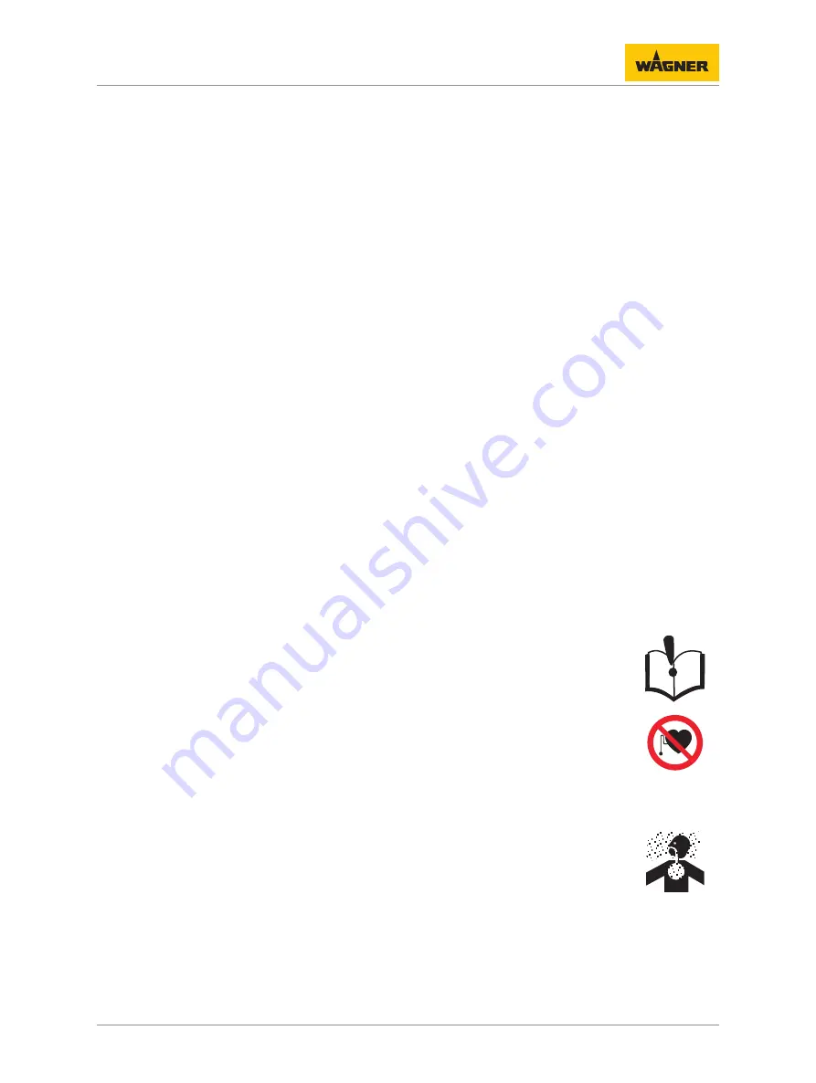
Danger due to high-voltage field!

Danger to life from malfunction of active implants.

4

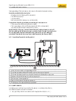
Persons belonging to a risk group according to EMF guideline 2013/35/EU (e.g., carriers
of active implants), must not enter the high-voltage area.

4.2.1   Personal Safety Equipment

Danger due to dust formation!

Serious or fatal injuries due to inhalation, swallowing or contact with the skin or eyes.

4

Observe the processing regulations laid down by the manufacturer of the powder
lacquer being used, when preparing or processing the powder.

4

Take note of the manufacturer’s notification and the relevant environmental protection
regulations when disposing of powder lacquers.

4

Take the specified protective measures, in particular wear safety goggles, protective
clothing and gloves, as well as skin protection cream if necessary.

4

Use a mask or breathing apparatus if necessary.

Summary of Contents for PEM-X1 CG

Page 1: ...lation of the Original Operating Manual 0102 II 2 D 2mJ For professional use Always observe the information in this manual particularly the safety instructions and the warning instructions Store the m...

Page 2: ......

Page 3: ...or 12 4 1 1 Electrical Devices and Equipment 12 4 1 2 A Safe Work Environment 12 4 1 3 Personnel Qualifications 13 4 2 Safety Instructions for the Personnel 13 4 2 1 Personal Safety Equipment 13 4 2 2...

Page 4: ...0 8 2 Maintenance 30 8 2 1 Maintenance Personnel 30 8 2 2 Maintenance Instructions 31 8 2 3 Safety Checks 31 8 2 4 Maintenance Procedures 31 8 3 Changing the Cup Gun 32 8 4 Changing the Flat Jet Nozzl...

Page 5: ...2 12 5 Wedge tool 52 12 6 Wall mount 53 12 7 Recipe sticker 53 12 8 Powder measuring adapter 53 12 8 1 Powder Measuring Adapter for X1 Flat Jet Nozzle 54 12 9 PEM X1 CG portable set 54 13 Spare Parts...

Page 6: ...all into the following categories DANGER Immediate risk of danger Non observance will result in death or serious injury WARNING Potential danger Non observance may result in death or serious injury CA...

Page 7: ...nslation of the original operating manual Language Order no Language Order no English 2326960 Polish 2410120 French 2326961 Croatian 2417169 Italian 2326962 Spanish 2326963 Russian 2333347 Chinese 233...

Page 8: ...gned to him her and detect possible hazards based on his her technical training knowledge and experience in rele vant provisions Skilled person in the context of DGUV 209 052 A person who based on his...

Page 9: ...Do not deactivate safety fixtures 4 Use only WAGNER original spare parts and accessories 4 The operating personnel must be trained on the basis of this operating manual 4 Follow the instructions in t...

Page 10: ...ody PTB Ex Symbol for explosion protection II Device class II 2 Category 2 D Ex atmosphere dust 2mJ Maximum ignition energy 2 mJ 3 2 FM APPROVAL P_00309 The PEM X1 CG powder cup gun is FM approved in...

Page 11: ...ISSIBLE DEVICE COMBINATIONS WARNING Incorrect use Risk of injury and damage to the device 4 Only connect the powder spray gun to original WAGNER devices Only use the PEM X1 CG powder gun cup with the...

Page 12: ...ore work is commenced 4 Secure the device against being switched back on without authorization 4 Inform personnel about planned work 4 Observe electrical safety regulations 4 Ground all devices to a c...

Page 13: ...nel Qualifications Danger due to incorrect use of device Risk of death due to untrained personnel 4 Ensure that the operating personnel has been instructed by the operator in accordance with the opera...

Page 14: ...y nozzle is installed or cleaned 4 2 3 Grounding the Device Danger due to electrostatic charge Explosion hazard and damage to the device The electrostatic charge may in certain cases give rise to elec...

Page 15: ...age to the device 4 Before starting cleaning or any other manual work the high voltage in the spray area must be shut down and locked to prevent it from being switched back on 4 Lock the compressed ai...

Page 16: ...h off the energy and compressed air supply 4 Relieve pressure on spray gun and device 4 Secure the spray gun against actuation 4 Observe the operating and service manual for all work 4 2 8 Protective...

Page 17: ...sical effect can be seen when the electrode is brought near the grounded work piece This luminous discharge does not involve any ignition energy and has no effect on system handling When the electrode...

Page 18: ...r air connection 10 Flat jet nozzle 5 Feed air connection 11 Suspension hook 6 Dosing air connection 12 Powder Cup 5 2 MODE OF OPERATION OF THE CUP GUN High voltage is activated in the manual gun when...

Page 19: ...ectrical Input voltage maximum 22 Vpp Input current maximum 0 9 A Frequency 19 30 kHz Output voltage maximum 100 kV DC Maximum Corona current 120 A Polarity negative positive special ac cessories Pneu...

Page 20: ...41 104 F Operating temperature range FM scope of applica tion 5 45 C 41 113 F Relative humidity 75 5 4 2 Dimensions A P_01726 B D C Measure ment mm inch A 365 14 37 B 230 9 06 C 290 11 42 D 45 1 77 Wi...

Page 21: ...e location must be between 20 C and 60 C 4 F and 140 F The relative air humidity at the storage location must be between 10 and 95 without condensation 6 3 INSTALLATION CONDITIONS The air temperature...

Page 22: ...width can be adjusted by the sliding ring P_03821 Sliding ring at rear wide cloud Cloud opening angle approx 80 P_03822 Sliding ring at front narrow cloud Cloud opening angle approx 60 P_03823 Sliding...

Page 23: ...number 2326960 Edition 10 2022 23 Deflector cone Application Distance to work piece mm R18 P_01665 18 mm Smaller flat parts 100 300 R25 P_01666 25 mm Medium sized flat parts 100 300 R34 P_01667 34 mm...

Page 24: ...up to stop 6 7 HOW TO USE THE POWDER CUP P_05500 2 1 3 Cover 1 is only needed on the gun if the gun is angled such that powder escapes from the tank During coating the flip flop latch 2 must be open I...

Page 25: ...nut are correctly fitted 3 Connect electrical cable of the cup gun to the control unit 4 Connect the feed air hose to the cup gun and to the control unit 5 Connect the dosing air hose to the cup gun...

Page 26: ...ntact points between conveyor conveyor hooks hangers and work piece are not sufficiently cleaned and therefore the work pieces are not sufficiently grounded These sparks can cause heavy radio frequenc...

Page 27: ...POWDER SPRAY GUN 1 To put the control unit into operation see corresponding operating manual 2 Hold the manual powder spray gun in the spray booth 3 Via the trigger lever of the manual powder spray gu...

Page 28: ...itation air volumes etc To access the function press the trigger lever on the manual gun twice in quick succession and hold down Upon releasing the trigger the original program will be returned to 2x...

Page 29: ...device If a prompt for pressure relief is given If coating work is interrupted or stopped Before the device is externally cleaned checked or serviced Before the spray nozzle is installed or cleaned 7...

Page 30: ...sh the Flush button on the control unit in order to switch off the cleaning function 5 Remove the powder cup from the cup gun 6 Clean the powder cup and powder cup s cover with compressed air 7 Unscre...

Page 31: ...dividual components for all work Prior to maintenance Flush and clean the system according to Chapter Cleaning Procedures 8 30 After maintenance Carry out safety checks in accordance with Chapter Safe...

Page 32: ...are parts list with must be regularly checked and replaced if necessary 6 4 5 2 1 P_01732 3 1 Switch off control unit 2 Disconnect electrical cable 1 from control unit 2 3 Disconnect dosing air hose 3...

Page 33: ...m from the gun body The nozzle system remains inserted in the union nut Note If the nozzle system doesn t remain inserted in the union nut the nozzle system and union nut must be replaced 3 The parts...

Page 34: ...spring contact of the gun body and contact surface of the electrode holder should be checked The spring contact must be clean and move easily the gun body must also be clean and free of powder deposi...

Page 35: ...e nozzle system from the gun body The nozzle system remains inserted in the union nut Note If the nozzle system doesn t remain inserted in the union nut the nozzle system and union nut must be replace...

Page 36: ...ector cone sleeve onto electrode holder 3 Insert electrode holder into gun housing 4 Slide union nut onto gun housing 5 Screw union nut onto gun housing hand tight 6 Slide deflector cone over deflecto...

Page 37: ...ut away view to improve comprehension 3 Protective wedge when positioned 1 Guide wedge tool 1 into electrode holder 2 up to stop 2 Pull protective wedge 3 out of electrode holder 2 using wedge tool 1...

Page 38: ...tive wedge remains inserted in the electrode holder Prior to re fitting check whether the contact points on the electrode holder and in the gun housing have been thoroughly cleaned so that the electro...

Page 39: ...79 1 Unscrew the union nut from gun housing 2 Remove the union nut with the nozzle system from the gun body The nozzle system remains inserted in the union nut Note If the nozzle system doesn t remain...

Page 40: ...deflector cone over deflector cone sleeve 8 8 ASSEMBLY OF THE CORONASTAR The CoronaStar is a retrofit set for the manual gun which helps to achieve a better surface quality e g reduction of orange pee...

Page 41: ...en fastening screws on rear of hook and unscrew 2 Slide hook in direction indicated by arrow and remove from gun housing 3 Fit new hook on receiver and slide in direction indicated by arrow 4 Fit fast...

Page 42: ...Unscrew screws 1 and remove connecting part 2 from gun body 2 Pull collector nozzle 3 out of gun body 3 Carefully insert new collector nozzle 3 in gun body 4 Attach connecting part 2 to gun body and f...

Page 43: ...2 3 1 2 P_01736 3 1 Remove the powder cup from the gun Unscrew screws 1 and remove connecting part 2 from gun body 2 Unscrew connecting tube 3 from gun body 3 Screw new connecting tube 3 into gun body...

Page 44: ...lt in the high voltage genera tor Contact a WAGNER service center Electrical cable from gun to con trol unit faulty Contact a WAGNER service center Cascade in gun faulty Contact a WAGNER service cente...

Page 45: ...ectrostatic coating with ignitable coating powders the test must be performed in accordance with DIN EN 50050 2 2013 according to the following Overview Table 8 46 10 1 ABBREVIATIONS ER Employer FT Fu...

Page 46: ...V Weekly 2 Link between technical ven tilation equipment and high voltage compressed air and powder feed The technical ventilation should be interlocked such that the powder feed and high voltage can...

Page 47: ...tem 3 Disconnect the gun connection cable from control unit 4 Disconnect the hose for feed air dosing air and atomizing air from the spray gun and from the control unit 11 2 DISPOSAL NOTICE Do not dis...

Page 48: ...in parentheses 12 1 1 Flat Jet Nozzles System X1 Order no K Designation 2429073 X1 electrode holder cpl ET white P_01691 Can be combined with 2420243 X1 flat jet nozzle F1 P_04985 2428515 X1 cross noz...

Page 49: ...te P_01666 2321171 Deflector cone D34 complete P_01667 Wearing parts 12 1 4 Nozzle extension P_01697 P_02163 X1 VL Nozzle Extension 150 300 500 X1 VL Nozzle Extension 750 Order no K Designation 232336...

Page 50: ...2324147 Flat jet nozzle X1 VL ET P_04995 Wearing parts 12 1 4 2 Round Jet Nozzles System Order no K Designation 2323461 Nozzle insert X1 VL R yellow P_04992 Can be combined with 2321981 Deflector con...

Page 51: ...CUP 12 2 1 Powder Cup 210 ccm P_01730 Order no K Designation 2324139 1 x cup with cover 2324140 5 x cup with cover Wearing parts 12 2 2 Powder Cup 1 Liter P_03877 Order no K Designation 2399466 1 x cu...

Page 52: ...8 Order no K Designation 2399470 2399470 12 4 RETROFIT SET CORONASTAR P_01695 1 Order no K Designation 2322868 CoronaStar PEM X1 complete 2322835 CoronaStar electrode PEM X1 ET 12 5 WEDGE TOOL P_01696...

Page 53: ...7 70 40 3 6 50 P5 P6 P7 P8 P9 P10 name 80 100 4 5 80 ______________________________ www www wagner group com industry ______________________________ 2x 82 20 3 6 45 P_01829 Order no K Designation 2331...

Page 54: ...asuring Adapter for X1 Flat Jet Nozzle P_04998 Order no K Designation 2428701 Universal powder measuring adapter complete 12 9 PEM X1 CG PORTABLE SET The PEM X1 CG portable set is mainly designed for...

Page 55: ...Operating manual Powder Cup Gun PEM X1 CG 12 Accessories Order number 2326960 Edition 10 2022 55 Operating position and connecting parts...

Page 56: ...K marking in the following spare parts lists Wearing parts Wearing parts are not included in the warranty Included in service set Not part of the standard equipment but available as a special accessor...

Page 57: ...EM X1 CG CORONA CUP GUN 1 2 3 4 5 13 P_01737 6 8 9 10 11 12 7 Pos K Stk Order no Designation 1 1 2322588 PEM X1 CG Corona Cup Gun 2 1 2320464 Union nut X1 3 1 2321976 Flat jet nozzle X1 complete 4 1 2...

Page 58: ...3 Non return valve complete 1 2343544 Hose kit PEM X1 CG ET Wearing parts Available as an accessory not included in the scope of delivery 13 4 X1 R ELECTRODE HOLDER 4 3 5 6 7 P_01700 2 1 Pos K Stk Ord...

Page 59: ...4 1 2 3 Pos K Stk Order no Designation 1 1 2324139 1 x cup with cover 2 1 2324140 5 x cup with cover 3 1 2323145 Cup X1 4 1 2322906 Cover 13 6 CONNECTING PART 1 2 P_01738 Pos K Stk Order no Designatio...

Page 60: ...PEM X1 CG 13 Spare Parts 60 Order number 2326960 Edition 10 2022 Pos K Stk Order no Designation 1 1 2324135 Connecting tube ET 2 1 9971445 O ring 3 1 2324133 Collector nozzle ET 4 1 9974210 O ring 5...

Page 61: ...000 6 4 2019 EN 60529 1991 A1 2000 A2 2013 EN IEC 63000 2018 Applied national technical standards and specifications in particular DGUV I 209 052 TRGS 727 Identification 0102 II 2 D 2mJ PTB 12 ATEX 50...

Page 62: ...Operating manual Powder Cup Gun PEM X1 CG 14 Declaration of Conformity 62 Order number 2326960 Edition 10 2022...

Page 63: ......

Page 64: ...lephone 49 0 7544 5050 Fax 49 0 7544 505200 E mail ts powder wagner group com Switzerland Wagner International AG Industriestrasse 22 CH 9450 Altst tten Telephone 41 0 71 757 2211 Fax 41 0 71 757 2222...

Reviews: