


7 Placing into operation
Installation location
Position mortar spraying machine in a level position to
prevent it from sliding away.
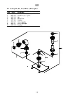
Compressor (accessory)
Attach compressor holder to the mortar spraying
machine. Place compressor onto holder and secure with
screws. Connect compressor to power supply.
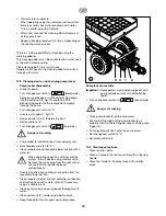
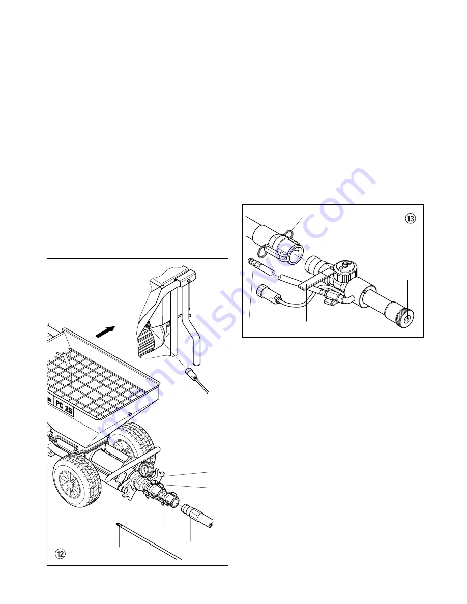
Connecting mortar hose
• Check that the outlet unit (1, fig. 12) is seated firmly. If
necessary tighten star grips (2) by hand.
• Connect mortar hose (3) and secure with tension
levers (4).
• Screw remote control to connection (5) on the control
unit.
• Connect atomization air connection (6) on mortar hose
to the compressed air supply or compressor
(accessory).
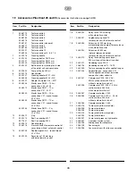
Connecting spray lance with automatic system
• Assemble texture nozzle (1, fig. 13) on the spray lance
with cone in the direction of the spraying head.
The nozzle size should be at least three times the
grain size,
e.g., grain size synthetic resin plaster –> 3 mm
nozzle size
–> 10 mm
• Connect spray lance (2) and secure with tension
levers (3).
• Close material tap (4).
• Screw coupling plug (5) for remote control to the
control cable of the mortar hose.
• Connect atomization air connection (6) to the air hose
of the mortar hose.
Connecting spray lance without automatic system
• Fasten remote control switch (1, fig. 14) with the two
O-rings (2) to the mortar hose.
• Screw coupling plug (3) for remote control on the
control cable of the mortar hose.
• Assemble texture nozzle (4) on the spray lance with
cone in the direction of the spraying head.
The nozzle size should be at least three times the
grain size,
e.g., grain size synthetic resin plaster –> 3 mm
nozzle size
–> 10 mm
•
Connect spray lance (5) and secure with tension
levers (6).
•
Close material tap (7).
•
Connect atomization air connection (8) to the air
hose of the mortar hose.
34
g
6
3
4
1
2
5
2
6
4
3
1
5
Summary of Contents for Plast Coat 25
Page 1: ...Ow n e r s Ma n u a l...
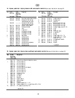
Page 10: ...Tabelle Teil 1 32 g...
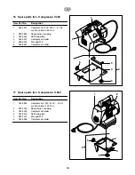
Page 11: ...Tabelle Teil 2 33 g...


