background image

42

g


1

0348 363

0348 363

Motor cable

  2

9982 820

9982 820

Cable screw connection

  3

9982 823

9982 823

Adapter

  4

0348 230

–––––––

Transmission motor 230 V

, 50 Hz

–––––––

0348 231

Transmission motor 400 V, 50 Hz, V3

  5

9900 204

9900 204

Hexagon screw M 8 x 35 DIN 931 (2)

  6

9920 102

9920 102

Washer A 8,4 DIN 125

  7

9900 125

9900 125

Hexagon screw M 8 x 50 DIN 933

  9

0348 334

0348 334

Supporting ring

10

9972 331

9972 331

Grooved ring 32 x 50 x 10

11

0348 400

0348 400

Intermediate flange

12

9971 171

9971 171

O-Ring 90 x 3,5

14

9930 913

9930 913

Straight pin 8 x 40

15

0348 324

0348 324

Screw

16

9921 518

9921 518

Lock washer B12 DIN 127

17

0348 313

0348 313

Carrier bush

18

9922 746

9922 746

Snap ring A 45

19

0348 314

0348 314

Feed screw

21

0348 329

0348 329

Grating

22

0348 307

0348 307

Receptacle

23

9900 109

9900 109

Hexagon screw M 8 x 25 DIN 933

24

0348 396

–––––––

Type plate PlastCoat 25

–––––––

0348 397

Type plate PlastCoat 35

25

9910 107

9910 107

Hexagon nut M8 DIN 934

26

0348 310

0348 310

Receptacle seal

27

0348 306

0348 306

Receptacle lower part

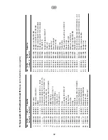
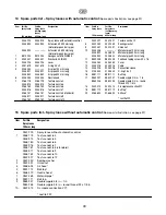
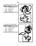
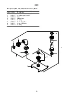
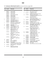
13  Spare parts list PlastCoat 25 and 35 

(Spare parts illustration, see page 96)

30

9910 208

9910 208

Hexagon nut M 8 DIN 985

31

9900 118

9900 118

Hexagon screw M 8 x 30 DIN 933

32

0348 316

0348 316

Pump screw yellow W 10/3 (standard)

33

0348 315

0348 315

Pump jacket yellow W 10/3 (standard)

34

9990 368

9990 368

Star grip M 16

35

0342 321

0342 321

Adapter fix-nipple V 35-M 27

36

0348 233

0348 233

Outlet unit

37

9990 618

9990 618

Coupling

38

9970 109

9970 109

Sealing ring

39

9991 946

9991 946

Pressure gauge

40

9991 947

9991 947

Protective cap

41

0348 349

0348 349

Wheel

42

9994 902

9994 902

Wheel cap

43

0348 419

0348 419

Trolley frame

44

9900 317

9900 317

Cheese head screw M 8 x 50 DIN 912

45

9990 863

9990 863

Pipe end cap

46

0348 318

0348 318

Drawbar tube right

47

9920 103

9920 103

Washer A 6,4 DIN 125

48

9910 204

9910 204

Hexagon nut M 6 DIN 985

49

0348 347

0348 347

Drawbar pipe left

50

0348 422

–––––––

Device mains connection H07 RN-F3G2,5 – 6 m

–––––––

0348 424

Device mains connection H07 RN-F5G1,5 – 6 m

51

9982 822

9982 822

Cable screw connection

52

9951 063

9951 063

Hexagon nut

53

9951 078

9951 078

Hexagon nut

Item

Part No.

Part No.

Designation

PlastCoat 25

PlastCoat 35

Item

Part No.

Part No.

Designation

PlastCoat 25

PlastCoat 35

Summary of Contents for Plast Coat 25

Page 1: ...Ow n e r s Ma n u a l...

Page 2: ...tributing point e g using a site distribution system with fault current protection with INF 30 mA PlastCoat 35 Only connect to the mains supply using a special distributing point e g using a site dist...

Page 3: ...ssor 37 9 2 Sack mangle 37 38 Using coating materials in sacks 38 9 3 Container suction system 38 Page 10 Placing out of operation and cleaning 38 10 1 Cleaning the mortar hose 38 39 10 2 Cleaning dev...

Page 4: ...ust be observed For safe operation of the mortar spraying machines always comply with the following specific instructions 1 Use of the mortar spraying machines The mortar spraying machines PlastCoat 2...

Page 5: ...ze 5 Insulation plaster Renovating plaster Foam mortar coating Quartz plastic Roof coatings Flameproof coatings Mineral sealing slurries Bitumen emulsions Reinforcing filler Liquid wood chip Frame sea...

Page 6: ...nozzle 10 Spray lance with automatic control 11 Switch sleeve for switching the mortar spraying machine on and off using remote control 12 Spray lance without automatic control 13 Remote control switc...

Page 7: ...hangeover switch fig 4 1 Releasing the pressure or removing the pump jacket Pump runs in reverse direction 2 0 drive is switched off 3 AUTO remote control using the spray lance 4 Spraying or pulling o...

Page 8: ...360 l min fig 6 1 Compressor holder 2 Compressed air connection Note Only operate the compressor according to the operating manual included C 350 suction volume 350 l min fig 7 1 Compressor holder 2...

Page 9: ...y lance without automatic control fig 10 1 Atomization air connection 2 Air tap 3 Texture nozzle 4 Material tap 5 Material connection Various different texture nozzle can be fitted to the spray lance...

Page 10: ...Tabelle Teil 1 32 g...

Page 11: ...Tabelle Teil 2 33 g...

Page 12: ...ying head The nozzle size should be at least three times the grain size e g grain size synthetic resin plaster 3 mm nozzle size 10 mm Connect spray lance 2 and secure with tension levers 3 Close mater...

Page 13: ...tic resin products synthetic resin dispersion PCC systems cellulose paste Fill 2 3 l synthetic resin dispersion or cellulose paste into the receptacle Caution set changeover switch 4 fig 15 to 0 befor...

Page 14: ...e separately Do not kink the mortar hose Protect it against damage e g resulting from it being run over or from sharp objects Starting the spraying procedure Open air tap 2 fig 16 and 17 and material...

Page 15: ...ace Note Sharp edged grains and pigments will increase wear on the pump hose material ball valve and tip 9 Fitting accessories 9 1 Compressor V 400 suction volume 360 l min Attach compressor holder it...

Page 16: ...container Turn on mortar spraying machine Note All connections must be sealed air tight so that a vacuum can be produced Place a small amount of machine lubricant onto the rubber seals of the connect...

Page 17: ...3 will disconnect from pump screw Set changeover switch to 0 Clean receptacle and receptacle lower section with a water jet When operating using the container suction system turn off device using mast...

Page 18: ...before turning on master switch Set delivery rate switch to 0 Set changeover switch to forward As soon as the pump screw rotates at a constant speed slowly set the delivery rate switch to the desired...

Page 19: ...witch and changeover switch to 0 Turn mortar spraying machine back on after about 20 sec Caution set changeover switch to 0 before turning on master switch If none of the above mentioned possible caus...

Page 20: ...3 Spare parts list PlastCoat 25 and 35 Spare parts illustration see page 96 30 9910 208 9910 208 Hexagon nut M 8 DIN 985 31 9900 118 9900 118 Hexagon screw M 8 x 30 DIN 933 32 0348 316 0348 316 Pump s...

Page 21: ...omatic control 1 0268 779 Texture nozzle 4 0348 915 Texture nozzle 5 0268 780 Texture nozzle 6 0348 916 Texture nozzle 7 0268 781 Texture nozzle 8 standard 0348 917 Texture nozzle 9 0268 782 Texture n...

Page 22: ...0348 957 Compressor holder 16 Spare parts list Compressor V 400 Item Part No Designation 5 5 2 1 6 3 4 1 0348 955 Compressor C 350 230 V 50 Hz suction volume 350 l min 2 9993 040 Rapid action coupling...

Page 23: ...uction system Item Part No Designation 1 0348 907 Container suction system 2 0097 100 Seal 3 0342 205 Suction hose 4 0097 085 Coupling 5 0348 361 Connecting plate 6 0348 947 Connecting bridge 7 0097 1...

Page 24: ...le nipple 3 4 in round thread 32 x 1 8 in 15 0342 200 Spray lance 100 mm long without automatic control Item Part No Designation 16 0348 224 Spray lance 100 mm long with automatic control 17 0348 931...

Page 25: ...430528 A B Wagner Spraytech Iberica S A Apartado 132 08750 Molins de Rey Barcelona Spain Phone 93 6800028 Fax 93 6680156 J Wagner France S A R L B P 75 91122 Palaiseau Cedex France Phone 01 60114050 F...

Reviews: