background image

41

Plast Coat 25 · 35

GB

10.2 

CleANING deVICe ANd CHANGING PuMP 

jACket

Never remove the safety grill for any clea-

ning work!

disassembly

•  Lubricate pump. 


Turn  changeover  switch  to 

(backwards).  

Spray pump antiseize or a little dishwashing liquid into the 

outlet unit (2, fig. 22) or place a little dishwashing liquid into 

the receptacle and pump through the pump.

•  Turn changeover switch to „0“.

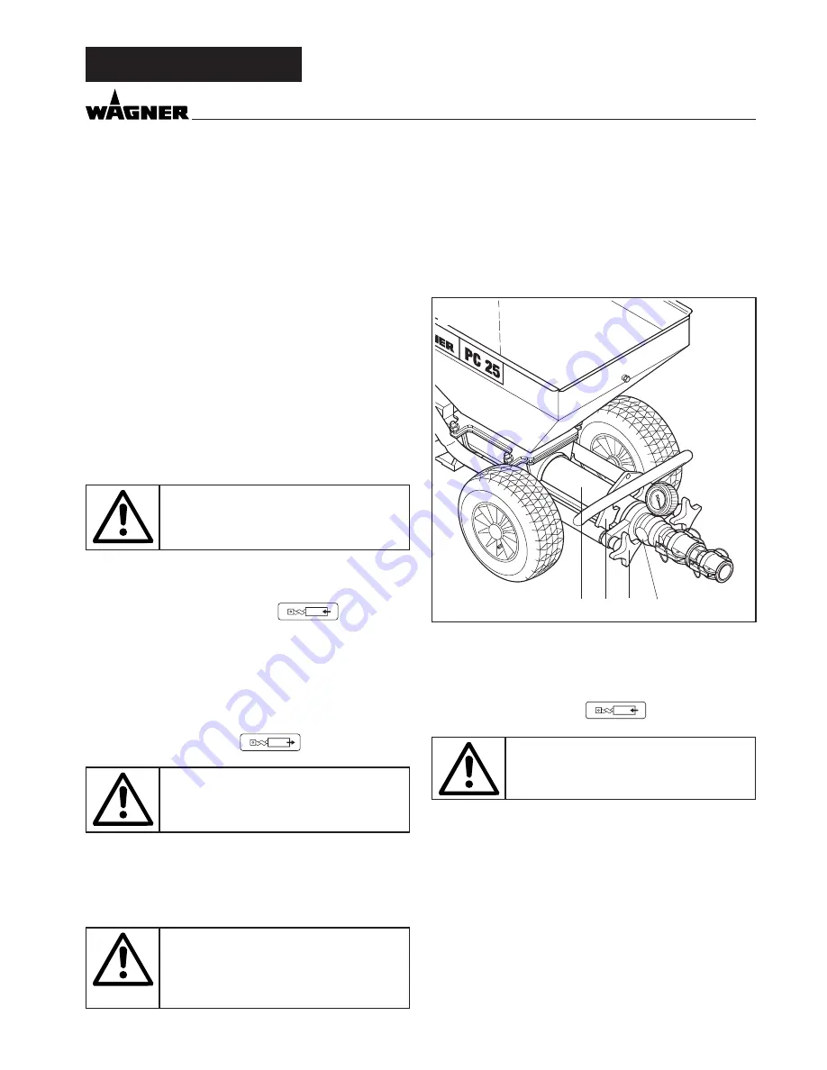
•  Unscrew star grips (1, fig. 20).

•  Remove outlet unit (2) towards the front.

•  Set feed rate to „3“.
•  Turn changeover switch to 

(forwards). 

danger of crushing!

•  Pump jacket (3) will disconnect from pump screw.

•  Set changeover switch to „0“.

•  Clean receptacle and receptacle lower section with a water 

jet.

When operating using the container suc-

tion system, turn off device using master 

switch. Remove the mains plug from the 

socket and ensure that it cannot be re-

placed unintentionally.

•  Unscrew and remove container connection from the recep

-

tacle lower section.

•  Clean  receptacle  lower  section,  container  connection  and 

suction hose with a water jet and, if necessary, using a suit-

able brush.

•  Clean pump screw and pump jacket thoroughly with water.

•  Clean outlet unit (2) inside using a bottle brush.

•   Keep threads for the star grips clean and grease.

Pump jacket assembly

Important:

Spray pump screw and pump jacket with pump antiseize or 

wet with dishwashing liquid.

•  Turn changeover switch to 

(backwards). 

danger of crushing!

•  Place pump jacket (3, fig. 20) onto pump screw. Ensure that 

the ledge of the pump jacket (3) is properly slid into the rec-

tangular recess of the pump trigger (4).

•  Pump jacket pulls itself onto the pump screw.

•  Set changeover switch to “0”.

•  Assemble outlet unit.

10.3 

CleANING SPRAy lANCe

•  Clean texture nozzle.

•  Clean air holes in the texture nozzle with a cleaning needle.

•  Clean the inside of the spray lance with a bottle brush.

•  Disconnect the mortar hose from the outlet section.

•  Insert cleaning ball in the mortar hose.   


Re-connect the mortar hose.

•  Fill water into receptacle.


When operating using the container suction system, im-

merse suction hose into receptacle with water.  

Turn on mortar spraying machine.

•  After a few seconds the cleaning ball will come out of the 

spray lance.

•   Repeat  cleaning  procedure  3–4  times,  depending  on  the 

coating material used.

There is a further possibility for cleaning using the cleaning 

adapter. 

This cleaning adapter can be connected to a water hose or 

tap with a claw coupling. 

Place cleaning ball in the mortar hose. Couple mortar hose to 

the cleaning adapter and rinse through with water.

placIng out of operatIon and cleanIng

3

2

1

4

Summary of Contents for Plast Coat 25

Page 1: ...Plast Coat PC 25 PC 35 0348 870 03 2010 Betriebsanleitung p 2 Operating manual p 24 Mode d emploi p 48 Gebruiksaanwijzing p 72...

Page 2: ...n the Operating manual 1 Only connect to the mains supply using a special distributing point e g using a site distribution system with fault current protection with INF 30 mA 2 Observe the permissible...

Page 3: ..._______ 38 9 Fitting accessories ____________________ 39 40 9 1 Compressor__________________________________ 39 9 2 Sack mangle_ ________________________________ 39 Using coating materials in sacks___...

Page 4: ...nnect to the mains supply using a special dis tributing point e g using site distribution system with fault current protection with INF 30 mA 7 The master switch has an EMERGENCY OFF function Danger o...

Page 5: ...esin bonded Filler synthetic resin bonded Concrete trowel All coating materials should be suitable for applying using machines See product data sheet for the coating material to be used Only use other...

Page 6: ...0 Spray lance with automatic control 11 Switch sleeve for switching the mortar spraying machine on and off using remote control 12 Spray lance without automatic control 13 Remote control switch for sw...

Page 7: ...1 1 Symbols on the changeover switch fig 4 1 Releasing the pressure or removing the pump jacket Pump runs in reverse direction 2 0 drive is switched off 3 AUTO remote control using the spray lance 4 S...

Page 8: ...employed instead of the receptacle 4 4 Compressor accessory V 400 suction volume 360 l min fig 6 1 Compressor holder 2 Compressed air connection Note Only operate the compressor according to the oper...

Page 9: ...e spray lance see accessories page 48 item 1 The size of the nozzle depends on the grain size of the coating material and the required spraying pattern 5 Transport Moving the mortar spraying machine o...

Page 10: ...piece 1 1 1 1 1 1 1 0342 255 Mortar hose DN 19 2 m Spray lances and nozzles 0348 241 0342 200 Spray lance with automatic control Spray lance without automatic control 0348 960 Ceiling spray lance wit...

Page 11: ...eral special scraped rendering PCC fine cavity filler PCC seal elastic slurries PCC renovating mortar up to G 4 Quartz containing elastic slurries Flameproof coatings Roof coating Bitumen sealing Spec...

Page 12: ...spraying head The nozzle size should be at least three times the grain size e g grain size synthetic resin plaster 3 mm nozzle size 10 mm Connect spray lance 2 and secure with tension levers 3 Close m...

Page 13: ...plings and plugs are in complete working order Arrange the mains cable so that there is no danger of it being tripped over Protect against damage e g caused by it being run over Before connecting to t...

Page 14: ...ress remote control switch 1 fig 16 on mortarhose Wait 3 5 seconds Close material tap 3 fig 16 Spray lance with automatic control fig 15 Spray lance without automatic control fig 16 8 General requirem...

Page 15: ...5 Turn the star grips 3 to the right until they will go no further Turn crank and move sack mangle to the rear as far as it will go material delivery rate and air delivery rate fine texture larger air...

Page 16: ...rnatively connect connecting bridge 6 to the container connection 3 and connect suction hose 5 to connecting bridge Fill suction hose with water and connect to the container Turn on mortar spraying ma...

Page 17: ...for the star grips clean and grease Pump jacket assembly Important Spray pump screw and pump jacket with pump antiseize or wet with dishwashing liquid Turn changeover switch to backwards Danger of cr...

Page 18: ...back into receptacle Mortar hose must be without pressure Observe pressure gauge 0 bar Wear protective goggles Disconnect mortar hose bend the blocked area by hand Rinse mortar hose with a water hose...

Page 19: ...t a larger texture nozzle If none of the above mentioned possible causes was the reason for malfunction there must be a defect which will be repaired by the WAGNER after sales service Malfunction chec...

Page 20: ...rating 27 0348 306 0348 306 Receptacle lower part 30 9910 208 9910 208 Hexagon nut M 8 DIN 985 31 9900 118 9900 118 Hexagon screw M 8 x 30 DIN 933 Item Part No PlastCoat 25 Part No PlastCoat 35 Design...

Page 21: ...ong 0348 922 0348 922 Material pipe 800 mm long 0348 943 0348 943 Material pipe 500 mm long 11 9902 309 9902 309 Pan head tapping screw 4 2 x 16 12 0348 460 0348 460 Cover 13 0348 216 0348 216 Cable 1...

Page 22: ...rt No Designation 1 0342 231 Compressor V 400 230 V 50 Hz suction volume 360 l min 2 9992 823 Rapid action coupling 3 0348 452 Retaining plate 4 0348 442 Compressor holder 5 9990 373 Star grip M 8 6 0...

Page 23: ...m Item Part No Designation 1 0348 907 Container suction system 2 9971 529 Seal 3 0342 205 Suction hose 4 0097 085 Coupling 5 0348 361 Connecting plate 6 0348 947 Connecting bridge 7 0097 105 Coupling...

Page 24: ...ithout automatic control Item Part No Designation 14 9983 238 Double nipple 3 4 in round thread 32 x 1 8 in 15 0342 200 Spray lance 100 mm long without au tomatic control 16 0348 241 Spray lance 100 m...

Page 25: ...49 Plast Coat 25 35 GB...

Page 26: ...3 22 24 6 40 38 42 43 41 36 50 44 45 3 1 2 4 9 11 14 7 17 18 15 12 19 26 27 6 31 15 32 33 35 30 6 10 30 30 37 49 46 53 47 16 16 48 6 25 39 5 34 2 6 21 d Ersatzteilbild GB Spare parts illustration F Ec...

Page 27: ...c commande autom NL Afbeelding onderdelen spuitlans met automaat 14 7 1 8 9 4 21 19 20 22 2 3 5 4 6 10 11 12 15 13 11 17 18 16 d Ersatzteilbild Spritzlanze ohne Automatik GB Spare parts illustration S...

Page 28: ...99 Plast Coat 25 35 16 21 1 2 3 4 5 7 15 20 6 19 24 10 17 13 22 11 8 12 9 18 17 23 14 14 14 d Zubeh rbild GB Accessories illustration F Illustration des accessoires NL Afbeelding met toebehoren...

Page 29: ...100 Plast Coat 25 35 34 33 29 30 31 26 25 35 32 d Zubeh rbild GB Accessories illustration F Illustration des accessoires NL Afbeelding met toebehoren...

Page 30: ...ted and are subject to strict checks under Wagner quality assurance Wagner exclusively issues extended guarantees to commercial or professional users hereafter referred to as customer who have purchas...

Page 31: ...r than is intended abnormal ambient conditions unsuitable coating materials unsuitable operating conditions operation with the incorrect mains voltage supply frequency over operation or defective serv...

Page 32: ...109 Plast Coat 25 35...

Reviews: