


ProSpray 24
g
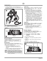
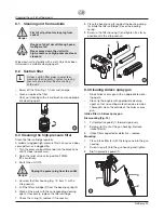
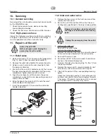
4. Fill in EasyGlide (Fig. 7). Do not fill in too much
EasyGlide, i.e. ensure that no EasyGlide drips into the
coating material container.
4.2
Control Panel Indicators
The following is a description of the control panel
indicators.
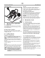
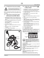
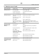
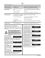
Pressure Indicator
The pressure indicator shows the current operating
pressure of the sprayer. It has three different
indications: blinking yellow, solid yellow, and solid
green.
Blinking Yellow
When the pressure indicator is blinking yellow, the
sprayer is operating between 0 and 1.4 MPa. A blinking
yellow pressure indicator means:
• The sprayer is plugged in and turned “ON”
• The sprayer is at priming pressure (little or no
pressure)
• It is safe to move the relief valve between positions
• It is safe to change or replace the spray tip
If the pressure indicator begins blinking yellow
when the pressure control knob is set at a higher
pressure and the relief valve is in the SPRAY posi-
tion, either the spray tip is worn or the sprayer is
in need of service/repair.
i
m
a
x
.
2
3
M
P
a
Ü
12 M Pa
Ü
23 M Pa
SER V I C E
P
N
0
5
5
1
8
8
3
Pressure
Indicator
Service
Indicator
Starting operation
Solid Yellow
When the pressure indicator is solid yellow, the sprayer
is operating between 1.4 and 12 MPa. A solid yellow
pressure indicator means:
• The sprayer is at the proper pressure setting for
spraying stain, lacquer, varnish, and multi-colors
• If the pressure indicator goes to solid yellow when
the pressure is set so that it starts at solid green, it
indicates one of the following:
a. Tip Wear Indicator — when spraying with latex or
at high pressure the solid yellow appears. This
means the tip is worn and needs to be replaced.
b. Tip Too Large — when a tip that is too large for
the sprayer is put in the gun, the pressure
indicator will turn from solid green to solid yellow.
c. Fluid Section Wear — if a solid yellow pressure
indicator appears when using a new tip and the
pressure is set at maximum, service may be
required (worn packings, worn piston, stuck valve,
etc...).
Solid Green
When the pressure indicator is solid green, the sprayer
is operating between 12 and 23 MPa. A solid green
pressure indicator means:
• The sprayer is at the proper pressure setting for
spraying oil-based and latex house paints
• The sprayer is operating at peak performance at a
high pressure setting
Service Indicator
The Service indicator is on when the motor is
commanded to run. This indicator is used by service
centers to troubleshoot motor problems.
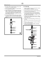
4.3
Pressure control knob settings
(Fig. 9)
1. Minimum pressure setting
2. Yellow zone – From minimum pressure to 120 bar
(12 MPa)
3. Green zone – From 120 bar (12 MPa) to 230 bar
(23 MPa)
4 White zone – no pressure generation
5. Blue zone – pulsating pressure for cleaning
m
a
x
.
2
3
M
P
a
Ü
12 M Pa
Ü
23 M Pa
SER V I C E
P
N
0
5
5
1
8
8
3
1
5
4
2
3


