


18
ProSpray 3.29 • 3.31
GB
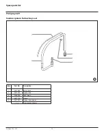
Repairs at the unit
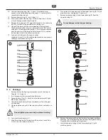
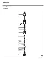
12. Insert upper packing (Fig. 15) with O-ring (1) and protruding
lip (2) downward into the upper housing (6).
1
2
13. Place intermediate ring (Fig. 14, Item 10) on the upper packing
(8).
14. Screw threaded joint (Fig. 14, Item 7) into the upper housing
(6) and tighten to 34 – 41 Nm.
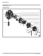
15. Insert lower packing (Fig. 16) in such a way that the side
with the smaller distance between the O-ring (1) and the
protruding lip (2) faces upward.
1
2
16. Move the lower packing to the end position using the
installation tool.
17. Push installation tool (included in scope of delivery of the
upper packing as a transportation device) for the piston (Fig.
14, Item 4) onto the piston from above.
18. Lubricate installation tool and piston (4) with machine grease.
19. Push piston (4) through the lower and upper packings until
the upper end of the piston protrudes from the threaded joint
(7).
20. Remove installation tool from piston (4).
21. Slide the top of the piston (4) into the T-slot (2) on the slider
assembly (3).
22. Screw lock nut (5) at the upper housing (6) until it touches.
23. Lubricate the threading of the upper housing (6) with
machine grease.
Remove upper housing from the vice.
24. Screw upper housing (6) into the gear unit housing until the
lock nut (5) touches and the connector for the connection
hose faces the rear.
25. Tighten lock nut (5) with light hammer blows.
26. Insert guide ring (11) into the lower housing (Fig. 13, Item 10)
and screw lower housing into upper housing and tighten.
27. Screw on and tighten connection hose.
28. Screw in inlet valve housing (Fig. 12, item 2), see Chapter 11.2,
Item 13.
29. Screw on and tighten suction tube.
30. Fasten return hose with clamp at suction tube.
31. Install front cover.
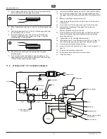
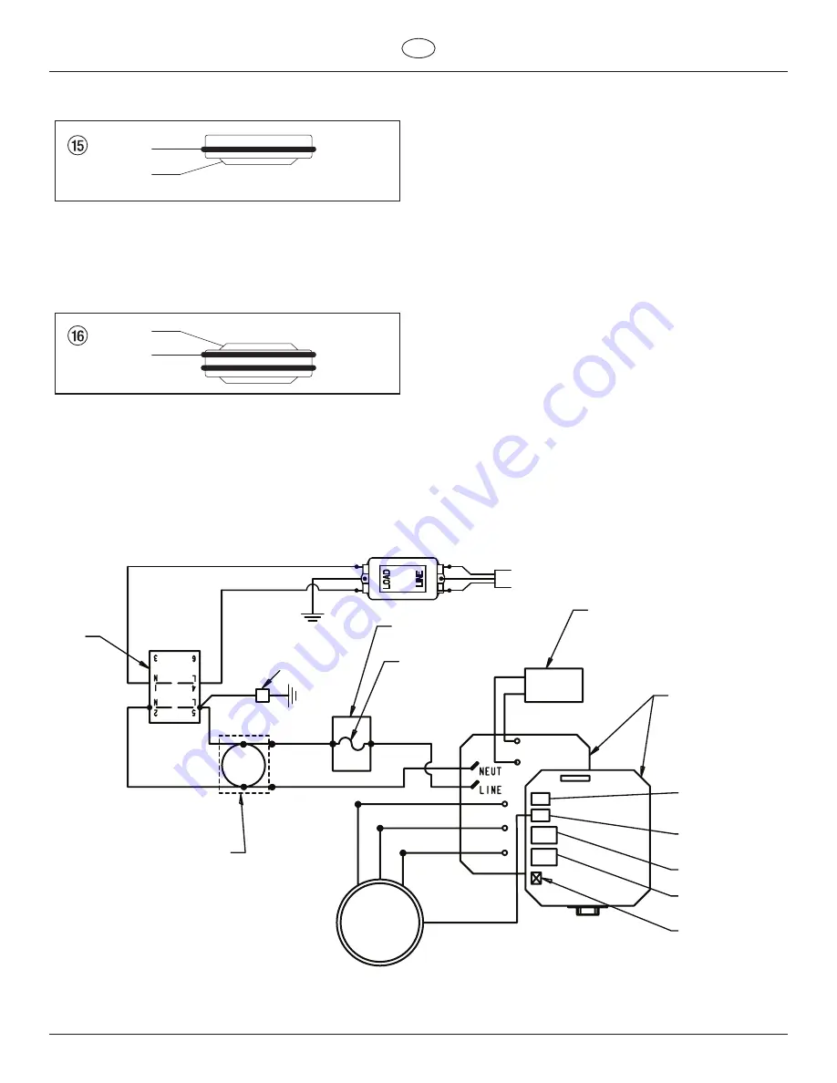
11.4 ProSpray 3.29 / 3.31 connection diagram
LOAD
LINE
EMI Filter
P/N 0522054
Ground
Switch
White
Black
Black
Black
Black
White
White
White
Red
Black
Black
Red
Red (+)
Black (-)
Black
Power Cord
Ground
Capacitor
Surge suppressor
P/N 0551972
Motor controller
Pressure sensor
L.E.D.
Hall sensor
Fuse block
Fuse
Potentiometer
Motor
Display wire assembly
(P/N 0522022)


