
15
OPERATING MANUAL
VERSION 07/2017
ORDER NUMBER DOC 2349369
6
ASSEMBLY AND COMMISSIONING
6.1
TRAINING OF ASSEMBLY/COMMISSIONING STAFF
The assembly and commissioning staff must have the technical skills to safely
commission the device.
When assembling, commissioning and carrying out all work, read and follow the
operating manuals and safety regulations for the additionally required system
components.
A skilled person must check to ensure that the device is in a reliable state after it is installed
and commissioned.
6.2
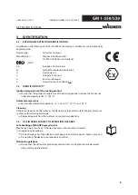
STORAGE CONDITIONS
Until the point of assembly, the device must be stored in a dry location, free from vibrations
and with a minimum of dust. The device must be stored in closed rooms. For ambient
temperature and air humidity, see Chapter
.
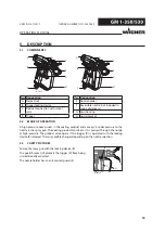
6.3
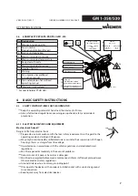
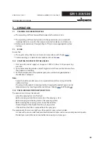
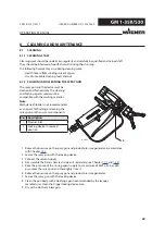
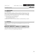
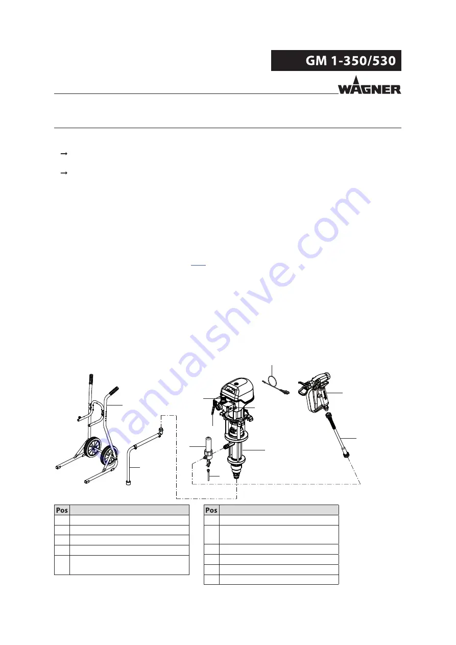
TYPICAL AIRLESS SPRAYING SYSTEM
The Airless manual gun PROTEC GM 1-350/530 must be combined with various components
to make up a spraying system. The system shown in the figure is only one example of an
Airless spraying system. Your WAGNER distributor would be happy to assist you in creating
a spraying system solution that meets your individual needs.
You must familiarize yourself with the operating manuals and the safety regulations for all
additional system components required before starting with commissioning.
A
B
C
D
E
G
H
J
I
K
B_05044
F
Designation
A Product pump
B Pressure air shut-off valve
C Pressure regulator
D Grounding cable
E High-pressure product hose,
electrically conductive
Designation
f Airless manual gun
G High-pressure filter/fluid pressure
release
H Return line
I Pump mounting trolley
J Suction system
K Compressed air main