background image

78

OPERATING MANUAL

VERSION 05/2017

ORDER NUMBER DOC 2354920

SPRINT XE

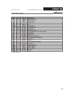
Pos K

Stk

Order No.

Designation

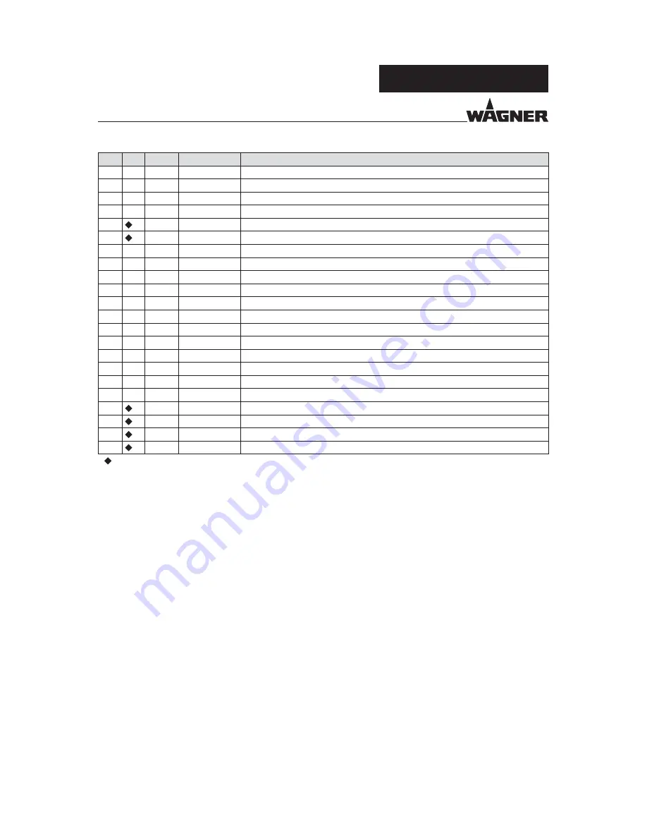
1

1

264268

Powder tank, 60 L

1

1

264224

Powder tank, 25 L

2

1

264215

Base housing

3

1

264381

Lid

4

1

264382

Fluidized bed

5

1.10 m

9971527

Foam rubber seal

6

6

9994703

Spring clip

7

12

9900717

Socket cap screw

8

1

9992270

Quick coupling for screw-on connector

9

1

184336

Hose fi tting

10

1

9910109

Hexagon nut

11

9982058

Exhaust hose, 17x3 mm

13

1

241372

Injector connection, complete

14

1

170533

Knurled nut

15

2

9920118

Washer

16

1

241276

Grounding cable, complete

17

12

9922102

Star washer

19

1

241376

Cable connection

20

1

263357

Intake tube, 60 L

20

1

264420

Intake tube, 25 L

21

1.10 m

8324008

Base seal

24

2

9971178

O-ring

   = Wearing parts

Summary of Contents for Sprint 60 L XE

Page 1: ...rating Manual SPRINT XE Manual Powder System For professional use Always follow the information in this manual particularly the safety instructions and the warning instructions Store the manual in a safe place Version 05 2017 P_02640 ...

Page 2: ......

Page 3: ... 3 Powder Spray Gun Type Plate 11 3 3 Permissible Device Combinations 12 4 BASIC SAFETY INSTRUCTIONS 13 4 1 Safety Instructions for the Operator 13 4 1 1 Electrical Devices and Equipment 13 4 1 2 A Safe Work Environment 14 4 1 3 Personnel Qualifications 14 4 2 Safety Instructions for Staff 15 4 2 1 Use Personal Safety Equipment 15 4 2 2 Safe Handling of WAGNER Powder Spray Devices 15 4 2 3 Ground ...

Page 4: ...fluid 40 7 2 3 Adjusting Fluidization 60 L Tank Without Vibrator Table 41 7 3 Factory Setting Recipe Nos 1 4 42 7 4 Interrupting the Coating Process 43 7 4 1 Airfluid Version 43 7 4 2 60 L Tank Version 44 7 5 Performing a Paint Change 45 7 5 1 Airfluid Version 45 7 5 2 60 L Tank Version 46 7 6 Double Click Recipe High Dynamic Remote 49 8 CLEANING AND MAINTENANCE 50 8 1 Cleaning 50 8 1 1 Cleaning S...

Page 5: ...s 67 13 2 Spare Parts List of Sprint Airfluid XE Manual Powder System 68 13 3 Spare Parts List of Sprint 60 L XE Manual Powder System Tank 70 13 4 Trolley Spare Parts 71 13 5 Intake Tube ST 550 10 72 13 6 Feed System SN 2 550 10 73 13 7 Compressed Air Supply 74 13 8 Powder Injector PI F1 75 13 9 HiCoat ED Pump F 76 13 10 60 L 25 L Tank 77 14 WEARING PARTS 79 15 Guarantee and Conformity Declaration...

Page 6: ...onnel 1 2 WARNINGS NOTICES AND SYMBOLS IN THESE INSTRUCTIONS Warning instructions in this operating manual highlight particular dangers to users and to the device and state measures for avoiding the hazard These warning instructions fall into the following categories DANGER Immediate risk of danger Non observance will result in death or serious injury WARNING Potential risk Non observance may resu...

Page 7: ...in the tasks assigned to him her the potential risks associated with improper behavior as well as the necessary protective devices and measures Electrically trained person Is instructed by an electrician about the tasks assigned to him her the potential risks associated with improper behavior as well as the necessary protective devices and measures Electrician Can assess the work assigned to him h...

Page 8: ...ice as a whole Do not deactivate safety fixtures Use only WAGNER original spare parts and accessories The operating personnel must be trained on the basis of this operating manual Follow the instructions in the operating manual 2 3 FOR USE IN POTENTIALLY EXPLOSIVE AREAS The device is suitable for use in potentially explosive areas as defined in Directive 2014 34 EU ATEX see Explosion protection ma...

Page 9: ... Device protection level suitable for use in Zone 22 T100 C Maximum surface temperature 3 1 2 CONTROL UNIT IDENTIFICATION The device is suited for use in potentially explosive areas in accordance withTest Certificate PTB 12 ATEX 5001 Device type EPG Sprint XE control unit Manufacturer Wagner International AG 9450 Altstätten Switzerland 0102 II 3 2 D CE European Communities 0102 Number of notified ...

Page 10: ...evice class II 2 Category 2 D Ex atmosphere dust 2mJ Maximum ignition energy 2 mJ The EC type examination certificates are listed in Chapter 15 4 3 2 TYPE PLATES 3 2 1 TROLLEY TYPE PLATE P_02655 CH 9450 Altstätten Made in Switzerland Wagner International AG II 3D Dc T100 C Typ Type Manual Unit SPRINT Handanlage SPRINT SPRINT Airfluid XE 2355400 SPRINT Airfluid XE Jap 2355800 SPRINT 60L XE 2355403 ...

Page 11: ...er input Netz eingang Mains output vibrator Netz ausgang Rüttler 6 8 bar 87 116 psi Clean and dry air Saubere und trockene Luft 6 5 2 ISO 8573 1 Do NOT disconnect when energized NICHT unter Spannung trennen I O Air input Lufteingang For operation all ports must be fitted with a plug or the protection cap Für den Betrieb in der Zone 22 müssen alle Anschlüsse mit Stecker oder Schutzkappe versehen se...

Page 12: ...iginal WAGNER control units and powder spray guns Only use the Sprint XE manual system with the following guns and control units Control units Guns EPG Sprint XE PEM X1 Corona spray gun PEM X1 CG PEM C4 Corona spray gun PEM C4 Ergo Corona spray gun PEM C4 Ergo Corona spray gun FM USA PEM T3 Tribo spray gun Tribo lance TL 1 Permissible device combinations for the USA and Canada see Chapter 15 5 FM ...

Page 13: ...luences May only be maintained by skilled electricians or under their supervision With open housings there is a danger from line voltage Operate device in accordance with the safety regulations and electrotechnical regulations Must be repaired immediately in the event of problems Decommission if it poses a hazard or is damaged Must be de energized before work is commenced Secure the device against...

Page 14: ... Ensure that there are no ignition sources such as naked flames sparks glowing wires or hot surfaces in the vicinity No smoking Maintain sufficient quantities of suitable fire extinguishers and ensure that they are serviceable The powder release must be electronically interlocked with the powder spray system exhaust equipment Excess coating product overspray must be collected up safely The operati...

Page 15: ...rotective measures In particular wear safety goggles protective clothing and gloves as well as hand protection cream if necessary Use a mask or breathing apparatus if necessary For sufficient health and environmental safety Operate the device in a powder coating booth or on a spraying wall with the ventilation extraction switched on 4 2 2 SAFE HANDLING OF WAGNER POWDER SPRAY DEVICES Danger due to ...

Page 16: ...ng system Parts of the booth must be grounded in accordance with EN 12981 Ensure that all persons inside the working area are grounded e g that they are wearing static dissipative shoes Grounding cables must be checked regularly to ensure that they are serviceable see EN 60204 4 2 4 PRODUCT HOSES Danger due to damaged product hoses The product hose may cause dangerous injuries Use only an original...

Page 17: ...least 15 K above the ambient temperature Only mobile industrial vacuum cleaners of design 1 see EN 60335 2 may be used for getting rid of dust build ups Take measures for workplace safety see chapter 4 1 2 4 2 6 MAINTENANCE AND REPAIR Hazard due to improper maintenance and repair Danger to life and equipment damage Only a WAGNER service center or a suitably trained person may carry out repairs and...

Page 18: ...val of protective and monitoring equipment Danger to life and equipment damage Protective and monitoring equipment must not be removed modified or rendered unusable Regularly check for perfect functioning If defects are detected on protective and monitoring equipment the system must not be operated until these defects are remedied ...

Page 19: ...uid air throttle 7 Vibration table Function The feed unit 4 is inserted directly into the original bundle The powder is fed through the powder injector 5 to the powder spray gun 3 Due to the special arrangement of the suction crown and the vibration of the tank a homogeneous powder air mixture is generated and maintained during the entire duration of the powder feed The powder quantity and the ele...

Page 20: ...er injector 5 the powder is transported from the tank 4 to the spray gun 3 By feeding fluid air into the fluid base of the powder tank 4 a homogeneous powder air mixture is generated and maintained during the entire process of the powder feed from the tank The powder quantity and the electrostatic charge of the color powder are regulated by the control unit 2 The fluid air setting is done using th...

Page 21: ...ory For more details see Chapter The set values for operating with the Tribo gun should be saved to individually selected recipe locations 5 2 INCLUDED ITEMS 5 2 1 VARIANTS Order No Designation 2355400 Sprint Airfluid XE manual system standard version 2355403 Sprint 60 L XE manual system standard version 2355402 Sprint Airfluid XE manual system US version 2355404 Sprint 60 L XE manual system US ve...

Page 22: ...tion G1 4 Connection hose diameter 18 5x12 5 mm Pressure range input air 0 6 0 8 MPa 6 8 bar 87 116 psi Air flow maximum 15 m h 529 63 cf h Sum of feed and dosing air 2 12 m h 70 6 423 7 cf h Gun air 0 05 4 5 m h 1 765 158 9 cf h WAGNER injector type PI F1 HiCoat ED pump F PI F1 S Compressed air quality according to ISO 8573 1 6 5 2 according to ISO 8573 1 2010 WARNING Exhaust air containing oil R...

Page 23: ...ution 5 20 μA Tribo current 0 5 μA resolution 0 5 μA Recipes 50 preset recipes Switch over from Tribo to Corona Automatic Connectable spray gun types WAGNER guns PEM X1 PEM C4 PEM C4 Ergo PEM C4 Ergo FM PEM T3 Tribo lance TL 1 Ambient conditions Operating temperature range 5 40 C 41 104 F Noise development 63 dB mains pressure 0 6 MPa 6 bar 87 psi ...

Page 24: ...ated display High voltage Lights up green Display range 0 100 kV Resolution 10 kV Single LED display Nominal voltage Bar display Working voltage 2 Illuminated display Corona or Tribo Current Lights up green Tribo scale When a Tribo gun is connected and selected Bar display When powder feed is activated Display range 0 5 μA Resolution 0 5 μA Corona scale When a Corona gun is connected and selected ...

Page 25: ... is selected 10 LED display recipe for Second Coating Lights up green when the recipe for Second Coating is selected 11 LED display recipe for Profiles Lights up green when the recipe for profile part is selected 12 LED display recipe for Double Click Lights up green when the recipe for Double Click is selected 13 LED display Fault Lights up when there is a fault on the device 14 LED display Autom...

Page 26: ... Resolution 0 05 m h 22 LED display Total Air Lights up yellow when the setting Total Air is selected 23 LED display Atomizing Ionizing and Tribo Air Lights up yellow when the setting Atomizing Ionizing and Tribo Air is selected 24 Universal control dial Dynamic digital control dial with 32 positions per revolution Adjustment speed is proportional to rotational speed Used to set Total air volume a...

Page 27: ...lope Lights up green Lower LED characteristic curve flat Middle LED characteristic curve medium Upper LED characteristic curve steep 33 Illuminated display Powder Quantity Lights up green Display range 0 100 Resolution 3 33 Single LED display Set point high voltage and powder are deactivated Bar display Actual value high voltage and powder are activated 34 Illuminated display Total Air Volume Ligh...

Page 28: ...T XE 36 Push button Powder Quantity To activate the function the powder quantity is set with rotary controller 24 and is indicated in LED display 19 Adjusting range 1 100 Resolution 1 37 LED display Powder Quantity Lights up yellow when the powder quantity is selected ...

Page 29: ...reliable state after it is installed and commissioned 6 2 STORAGE CONDITIONS Until the point of assembly the device must be stored in a dry location free from vibrations and with a minimum of dust The device must be stored in closed rooms The air temperature at the storage location must be between 20 C and 60 C 4 F and 140 F The relative air humidity at the storage location must be between 10 and ...

Page 30: ...wer trolley section 1 on a clean level surface 3 Place upper trolley section 2 on the two guide sleeves on the lower trolley section 1 press down gently until stop is reached and use nuts and bolts see detail to screw to lower trolley section tightening torque 25 Nm 18 44 lb ft 4 Mount the gun holder 3 see separate assembly manual 6 4 2 ASSEMBLING THE CONTROL UNIT 1 2 3 P_02644 4 Procedure 1 Caref...

Page 31: ...rator is responsible ensuring the required compressed air quality 6 5 1 CONNECTION REQUIREMENTS DANGER Danger from electric current Danger to life and equipment damage Switch off the main switch 1 on the rear of the equipment before connecting the equipment NOTICE Missing cover Protection class of device not guaranteed Themainsoutputsocketmustremainclosedinmanualsystemswithoutvibratormotor with th...

Page 32: ...32 OPERATING MANUAL VERSION 05 2017 ORDER NUMBER DOC 2354920 SPRINT XE 6 5 2 CONNECTING THE AIRFLUID MANUAL POWDER SYSTEM Detail A 11 P_02639 1 3 4 5 2 6 7 10 12 9 8 11 ...

Page 33: ...rol unit 8 Connect the hose transparent for the atomizing or Tribo air Bundle the two hoses and the gun cable with Velcro cable binders 9 Connectthecompressedairhose 12 5x18 5mm OrderNo 9981951 tothecompressed air connection G1 4 on the manual system 10 Connect the trolley grounding cable to the control unit Connect the control unit s grounding cable with the signal ground 11 Plug in the connectio...

Page 34: ...34 OPERATING MANUAL VERSION 05 2017 ORDER NUMBER DOC 2354920 SPRINT XE 6 5 3 CONNECTING THE 60 L TANK MANUAL SYSTEM P_03293 4 6 7 8 5 9 10 14 16 13 11 12 3 2 1 15 Detail A ...

Page 35: ...e powder feed hose 10 Plug in the gun connection cable on the control unit 11 Connect the hose transparent for the atomizing or Tribo air Bundle the two hoses and the gun cable with Velcro cable binders 12 Connect exhaust air hose to the connection on the powder tank The other end of the exhaust air hose must be routed to the extraction unit of the powder spray booth 13 Connectthecompressedairhose...

Page 36: ...ectric charging of the work piece very poor wrap around uneven coating back spraying to the spray gun i e contamination Prerequisites for perfect grounding and coating of a work piece are clean suspension of the work piece to be coated The grounding resistance of the work piece must not exceed 1 M Resistance to ground measured at 500 V or 1000 V Sparksbetweenconveyor conveyorhooks hangers andworkp...

Page 37: ...ground 4 Connect grounding cable to an uncoated metal part of the booth 5 Remove all paint from hooks and other hanger parts 6 Wear electrostatically conductive gloves 7 Wear electrostatically conductive footwear 8 The floor must be electrostatically conductive 6 7 SAFETY CHECKS A skilled person must check to ensure that the device is in a reliable state after it is installed and commissioned This...

Page 38: ...ating staff must be familiar with the potential risks associated with improper behavior as well as the necessary protective devices and measures Before work commences the operating staff must receive appropriate system training 7 2 WORK Ensure that The regular safety checks are carried out in accordance with Chapter 8 2 3 commissioning is carried out in accordance with Chapters 6 4 and 6 5 ...

Page 39: ...sition I After a few seconds the control unit is operational The system switches to recipe 1 Surface parts after every restart To switch the manual system off or on actuate the Standby push button 2 Note The fluid air must be adjusted using the throttle 3 when first commissioning the manual system The control unit automatically recognizes the type of gun connected There are 50 recipes available fo...

Page 40: ...rface Actuate the trigger of the spray gun for a short time and release it The vibrator motor and the fluid air overrun for 10 s factory setting This setting can be changed by the user if required see EPG Sprint XE control unit operating manual 5 Adjust the fluid air at the throttle 2 to the point that it makes the feed system sink into the powder due to its own weight Note The amount of fluid air...

Page 41: ...the Vibrator motor controller parameter on the control unit to ON to permanently activate the fluid air see the EPG Sprint XE control unit operating manual 4 Actuatethetriggerofthespraygunforashorttime and release it 5 Adjustthefluidairatthethrottle 2 untilfluidization is recognizable Note The amount of fluid air depends on the characteristics of the powder Avoid a build up of powder dust too much...

Page 42: ... 0 1 P02 Second coating Avoidance of spraying back 50 20 Soft 3 6 57 0 1 P03 Profi le part Penetration and reduced build up of edges 70 40 Soft 3 6 50 0 1 P04 Double click Small components 80 20 Soft 3 6 45 0 1 P05 50 variable individual 80 100 Standard 4 5 80 0 1 Notes Under normal conditions metallic powder can be processed well using recipes Nos 1 4 When operating the system with a Tribo gun th...

Page 43: ...85 EPG SPRINT X 0 10 20 30 40 50 Ø 12 10 11 9 8 m h 2 0 3 0 0 5 0 3 0 1 1 5 3 5 5 4 5 3 5 2 5 80 100 Tri 90 60 70 P_1789 H 17 Procedure 1 Release the trigger on the spray gun The high voltage and the powder feed are deactivated 2 Lift the feed unit up underneath the injector and lift it out of the tank until retaining clamp H swivels downwards 3 Lower the feed system into the parking position and ...

Page 44: ...idues P_01785 EPG SPRINT X 0 10 20 30 40 50 Ø 12 10 11 9 8 m h 2 0 3 0 0 5 0 3 0 1 1 5 3 5 5 4 5 3 5 2 5 80 100 Tri 90 60 70 17 Procedure 1 Release the trigger on the spray gun The high voltage and the powder feed are deactivated 2 Remove the injector from the holder to stop powder feed 3 Hold the gun in the spray booth and start the flush function by pressing the Flush button 17 The injector and ...

Page 45: ...nd swivel it to the right side so that no more powder is forwarded 4 Hold the gun in the spray booth and start the flush function by pressing the Flush button 17 The injector and hoses are flushed 5 Switch off control unit 6 Clean all powder feeding parts of the unit such as the spray gun the injector and the powder feed hose 7 Place an opened powder tank 25 30 kg 55 11 66 14 lbs with the new powd...

Page 46: ...are deactivated 2 Remove the injector from the holder to stop powder feed 3 Hold the gun in the spray booth and start the flush function by pressing the Flush button 17 The injector and hoses are flushed 4 Switch off control unit 5 Open the powder tank and clean all powder feeding parts of the unit such as the spray gun the injector the powder feed hose and the suction system 6 Clean the powder ta...

Page 47: ...p powder feed 3 Hold the gun in the spray booth and start the flush function by pressing the Flush button 17 The injector and hoses are flushed 4 Switch off control unit 5 Loosen the powder feed hose from the powder injector and clean the spray gun and the powder feed hose thoroughly 6 Loosen the blue dosing air hose and the red feed air hose from the powder injector 7 Disconnect the black fluid a...

Page 48: ...e the Powder Feed Quantity function by pressing the Powder Quantity button 36 4 Adjust the powder quantity to 0 with the universal rotary controller 24 5 Actuate the trigger and keep it actuated 6 Adjust the fluid air at the throttle until fluidization is recognizable Note The fluid air quantity is dependent on the powder condition Avoid a build up of powder dust too much fluid air in the powder t...

Page 49: ... on the spray gun for example to recoat parts using different parameters high voltage current limitation air volumes etc To access the function press the trigger lever on the spray gun twice in quick succession and hold down Upon releasing the trigger the original recipe will be returned to 2x P_01701 2x 2x kV 80 60 40 20 100 Tri Cor 5 4 3 2 1 120 80 40 20 10 μA 2x 2x kV 80 60 40 20 100 Tri Cor 5 ...

Page 50: ... regularly and carefully by qualified and trained staff They should be informed of specific hazards during their training The following hazards may arise during maintenance work Health hazard from inhaling powder lacquer Use of unsuitable tools and aids An authorized person must ensure that the device is checked for being in a reliable state after maintenance work is completed 8 2 2 MAINTENANCE IN...

Page 51: ...surethatthesystemisgrounded 8 2 4 MAINTENANCE PROCEDURES The maintenance intervals should be adapted by the operator depending on the level of use and if necessary the level of soiling If in doubt we recommend contacting WAGNER s specialist personnel Maintenance work Time stamp per shift weekly Blow out gun and check for sintering Check gun settings Check gun discharge pressure Blow out powder hos...

Page 52: ...ded 4 Hold the gun in the spray booth and start the flush function by pressing the Flush button 17 The injector and hoses are flushed 5 Switch off control unit 6 Remove the union nut on powder feed hose 3 and disconnect powder feed hose 3 from injector 4 7 Disconnectpowderfeedhose 5 red frominjector 4 8 Disconnect dosing air hose 6 blue from injector 4 9 Pullthefluidairhose black offsuctionconnect...

Page 53: ...e red feed air hose 4 from injector 1 7 Disconnect the blue dosing air hose 5 from the injector 1 8 Check powder injector for wear and replace worn parts if necessary The wearing and spare parts can be found in the powder injector s operating manual 9 Loosen the exhaust air hose 6 from the connection 7 of the powder tank 8 10 Pull the black fluid air hose 9 off the powder tank 8 11 Loosen the grou...

Page 54: ...ontact WAGNER Service Department Sputtering powder feed The flow rate in the powder feed hose is too low Increase the total feed and dosing air and readjust the ratio of the airs to each other The cross section of the powder feed hose is reduced by movement Use a powder hose that prevents the cross section from narrowing Select a hose with a thicker wall Fluctuations in the compressed air caused b...

Page 55: ...powder feed hose is clogged Blow through the powder feed hose The powder suction system in the powder tank is clogged Blow through the powder suction system The feed air hose is bent Straighten or replace the feed air hose The powder feed hose is kinked Straighten or replace the powder feed hose The feed unit does not sink into the powder The guide of the feed unit holder is jammed Enabletheguidet...

Page 56: ...pment and high voltage compressed air and powder feed The technical ventilation should be interlocked such that the powder feed and high voltage cannot be switched on while the technical ventilation is not working eff ectively SP FT Test whether the system is safely stopped and the powder feed supply air and high voltage are switched off when the ventilation is shut down annually 3 Checking the el...

Page 57: ...ly and decompress system 4 Separate the connection cable from the compressed air connection 5 Separate the grounding cable from the signal ground 11 2 DISPOSAL NOTICE Do not dispose of used electrical equipment with household refuse In accordance with European Directive 2012 19 EU on the disposal of used electrical equipment and its implementation in national law this product may not be disposed o...

Page 58: ...RINT XE 12 ACCESSORIES 12 1 FEED SYSTEM SN 2 550 10 P_00418 Order No Designation 265272 Feed system SN 2 550 10 12 2 MAINTENANCE UNIT P_01355 Order No Designation 2314265 Maintenance unit 2314308 Filter cartridge spare part 2314309 Fine filter cartridge spare part ...

Page 59: ...ion 2312543 Quick coupling set 935658 Compressed air hose 9 5 mm 12 4 ADAPTER PLATE SWITCHBOX P_01158 Order No Designation 2308079 Adapter plate switchbox 12 5 SPRAY GUN SWITCHBOX P_00670 Order No Designation 265911 Spray gun switchbox When alternately a Corona or a Tribo gun is operated 2313993 Hose black 4x6 mm ...

Page 60: ... screws 2 4 P_01183 2 Use screws 4 to screw adapter plate with fitted switchbox onto the back side of trolley s front plate P_02718 A B C Connection for Corona guns Connection for Tribo guns 3 Pull the spray gun cable out of the socket A on the control unit 4 Plug the switchbox s electrical cable B into the socket A on the control unit and secure it with the protective sleeve 5 Connect the spray g...

Page 61: ...n the front 2 Change the coating powder from Corona to Tribo 3 Disconnect the hose 2 transparent atomizing air from the Corona gun and connect it to the Tribo gun Tribo air 4 Disconnect the powder feed hose of the Corona spray gun from the powder injector and connect the Tribo gun hose to the powder injector 5 Set the switch C on the switchbox to Tribo 6 Switch on control unit with switch 1 on the...

Page 62: ...AL VERSION 05 2017 ORDER NUMBER DOC 2354920 SPRINT XE 12 6 PEM T3 MANUAL GUN P_01422 Order No Designation 351019 PEM T3 Tribo manual gun 12 7 PEM T3 EXTENSION P_00923 Order No Designation 260934 Nozzle extension PEM T3 ...

Page 63: ...Order No Designation 2370544 Retrofit set Tribo lance TL1 1000 2370545 Retrofit set Tribo lance TL1 1800 2370546 Retrofit set Tribo lance TL1 2800 2369617 Hose set TL 1 8 m 2369618 Hose set TL 1 12 m 2369619 Hose set TL 1 16 m 12 9 SWIVEL CASTERS SET P_01680 P_02648 Order No Designation 2324869 Swivel casters set ...

Page 64: ... mm 2310700 Powder hose 12 mm 12 11 SPRINT DUAL MANUAL COATING SET This accessory is used to operate two manual guns with the manual system The set consists of the control unit the manual gun a feed unit and different connecting parts and cables Order No Designation 2331417 Sprint dual manual coating set 12 12 WALL MOUNT P_01861 Order No Designation 2330223 Wall mount with bracket ...

Page 65: ...nworkingwithsmallcomponentsorsmallbatches themanualsystemcanbeconverted into a variant with a 3L vibrator table Note The conversion sets have no FM approval P_02649 P_02650 Sprint 60 L V Sprint 3 L V Order No Designation 2373856 Sprint XE 60L 230V 50Hz conversion set 2383231 Sprint XE 60L 115V 60Hz conversion set USA Japan 2373883 Sprint XE 3L 230V 50Hz conversion set 2383232 Sprint XE 3L 115V 60H...

Page 66: ...dual components is desired the operating manuals listed below can be resorted to This extended operating manual includes important notes regarding connecting commissioning and the operation e g paint change of the relevant components theveryimportantchapter MaintenanceandCleaning fortherelevantcomponents troubleshooting and error correction for the relevant components spare parts wearing parts and...

Page 67: ...elivery normal mail express delivery air freight courier etc Identification in spare parts lists Explanation of column K labeling in the following spare parts lists Wearing parts Note These parts are not covered by warranty terms Not part of standard equipment available however as additional extra DANGER Incorrect maintenance repair Danger to life and equipment damage Only a WAGNER service center ...

Page 68: ...control unit 9951116 Thermal delay fuse 2A included in EPG Sprint XE 3 1 241622 Powder injector PI F1 4 1 265281 Intake tube ST 550 10 5 1 2322587 PEM X1 manual gun 6 2306401 Sprint connection parts 6 1 1 2303714 Sealing coupling with anti kink spring 6 2 1 3 m 9982079 Hose black 6 mm 6 3 1 3 m 700370 Hose blue 8 mm 6 4 1 935973 Sealing coupling with anti kink spring 6 5 1 3 m 2302060 Hose red 8 m...

Page 69: ...NT XE 10 1 241270 Mains cable Europe 10 1 264626 Mains cable USA 10 1 264625 Mains cable Japan Not included in the scope of delivery please order separately 11 1 2331976 Sprint round spray spare parts starter set 11 1 2349959 Sprint fan spray spare parts starter set ...

Page 70: ...51116 Thermal delay fuse 2A included in EPG Sprint XE 3 1 241622 Powder injector PI F1 4 1 2322587 PEM X1 manual gun 5 2306401 Sprint connection parts 5 1 1 2303714 Sealing coupling with anti kink spring 5 2 1 3 m 9982079 Hose black 6 mm 5 3 1 3 m 700370 Hose blue 8 mm 5 4 1 935973 Sealing coupling with anti kink spring 5 5 1 3 m 2302060 Hose red 8 mm 5 6 1 935974 Coupling plug with anti kink spri...

Page 71: ...arter set 10 1 2349959 Sprint fan spray spare parts starter set 13 4 TROLLEY SPARE PARTS P_02652 2 3 1 5 7 6 8 9 4 Pos K Stk Order No Designation 1 1 2307117 Sprint injector bracket complete 2 1 2325026 intake tube bush 3 1 2325022 Retaining clamp 4 2 2362487 Pipe clamp capacitor seat vibrator motor 5 2 2305431 Adjustment foot 6 1 2305421 Nut 7 1 2303279 Guide bush 8 1 2330599 Gun holder 9 1 99508...

Page 72: ...ER DOC 2354920 SPRINT XE 13 5 INTAKE TUBE ST 550 10 2 3 4 5 1 P_01155 Pos K Stk Order No Designation 1 1 265281 Intake tube ST 550 10 2 1 265401 Fluid crown 3 1 265402 Fluid ring 4 1 2303716 Plug in fitting G1 8 5 1 2307727 Extension Wearing parts ...

Page 73: ...17 ORDER NUMBER DOC 2354920 SPRINT XE 13 6 FEED SYSTEM SN 2 550 10 2 1 3 P_00577 Pos K Stk Order No Designation 265272 Feed system SN 2 550 10 1 1 265401 Fluid crown 2 1 265402 Fluid ring 3 1 9999047 Plug in fitting G1 8 Wearing parts ...

Page 74: ... SPRINT XE 13 7 COMPRESSED AIR SUPPLY Rear view of the control unit 2 P_02720 3 1 Pos K Stk Order No Designation 1 1 2303294 Solenoid valve 2 2 way 2 1 2304119 Fluid air throttle 3 1 2305860 Filter precipitator 9981951 Compressed air connection hose 18 5x12 5 mm ...

Page 75: ...signation 241622 Powder injector PI F1 1 1 241225 Annular gap collector nozzle 2 1 241476 Hose sleeve 3 1 241466 Union nut 4 1 241923 Air nozzle 5 2 241460 Spring check valve 7 1 9970149 Sealing ring 8 1 9992709 Quick release plug 9 1 9992710 Quick release socket 10 1 9970150 Sealing ring 11 2 9974023 Sealing ring electrically conductive Wearing parts ...

Page 76: ...No Designation 241624 HiCoat ED pump F 1 1 241229 Collector nozzle low air 2 1 241479 Hose sleeve 3 1 241466 Union nut 4 1 241930 Air nozzle 5 2 241460 Spring check valve 7 1 9970149 Sealing ring 8 1 9992709 Quick release plug 9 1 9992710 Quick release socket 10 1 9970150 Sealing ring 11 2 9974023 O ring electrically conductive Wearing parts ...

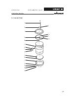
Page 77: ...77 OPERATING MANUAL VERSION 05 2017 ORDER NUMBER DOC 2354920 SPRINT XE 13 10 60 L 25 L TANK 13 11 3 19 20 1 6 7 17 4 21 2 8 14 15 16 9 5 10 P_01156 24 ...

Page 78: ...Spring clip 7 12 9900717 Socket cap screw 8 1 9992270 Quick coupling for screw on connector 9 1 184336 Hose fitting 10 1 9910109 Hexagon nut 11 9982058 Exhaust hose 17x3 mm 13 1 241372 Injector connection complete 14 1 170533 Knurled nut 15 2 9920118 Washer 16 1 241276 Grounding cable complete 17 12 9922102 Star washer 19 1 241376 Cable connection 20 1 263357 Intake tube 60 L 20 1 264420 Intake tu...

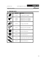
Page 79: ...ector cone 18 mm complete 2321980 Deflector cone 25 mm complete 2321171 Deflector cone 34 mm complete P_00696 260928 Fan spray nozzle for PEM T3 P_00697 259474 Deflector cone 22 mm for PEM T3 P_00723 265401 Fluid crown of suction unit P_00698 265402 Fluid ring of suction unit P_00699 241225 Clearance collector nozzle of PI F1 Injector P_01826 241229 Collector nozzle ED pump ...

Page 80: ...costs will be borne by us except where these costs are increased due to the subsequent shipment of the device to a location other than the address of the purchaser We do not provide warranty for damage that has been caused or contributed to for the following reasons Unsuitable or improper use faulty assembly or commissioning by the purchaser or a third party normal wear negligent handling defectiv...

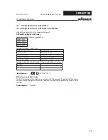
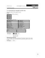
Page 81: ...ds in particular EN ISO 12100 2010 EN 13463 5 2011 EN 1127 1 2011 EN 61010 1 2010 EN 60079 0 2012 EN 60204 1 2006 A1 2009 EN 60079 31 2014 EN 61000 6 2 2005 EN 13463 1 2009 EN 61000 6 4 2007 A1 2011 Applied national technical standards and specifications in particular BGI 764 Identification II 3D Dc T100 C EU Declaration of Conformity The EU Declaration of Conformity is enclosed with this product ...

Page 82: ...177 2009 A1 2012 EN ISO 13849 1 2008 EN 1127 1 2011 EN 60529 1991 A1 2000 A2 2013 EN 60079 0 2012 A11 2013 EN ISO 12100 2010 EN 60079 31 2014 EN 61000 6 2 2005 EN 60204 1 2006 A1 2009 EN 61000 6 4 2007 A1 2011 Applied national technical standards and specifications in particular BGI 764 Identification II 3 2 D 0102 EU Declaration of Conformity The EU Declaration of Conformity is enclosed with this...

Page 83: ... 2011 EN ISO 12100 2011 EN 60079 0 2010 EN 61000 6 2 2011 EN 60079 7 2007 EN 61000 6 4 2011 EN 60079 31 2010 EN 62061 2010 EN 1953 2010 EN ISO 13849 1 2008 EN 60204 1 2007 EN 50177 2010 EN ISO 80079 34 2012 Applied national technical standards and specifications in particular BGI 764 Identification II 2D 2mJ 0102 PTB 12 ATEX 5002 EN 50050 2 2012 EU Declaration of Conformity The EU Declaration of C...

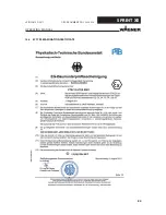
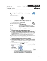
Page 84: ...84 OPERATING MANUAL VERSION 05 2017 ORDER NUMBER DOC 2354920 SPRINT XE 15 4 EC TYPE EXAMINATION CERTIFICATE ...

Page 85: ...85 OPERATING MANUAL VERSION 05 2017 ORDER NUMBER DOC 2354920 SPRINT XE ...

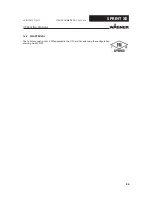
Page 86: ...86 OPERATING MANUAL VERSION 05 2017 ORDER NUMBER DOC 2354920 SPRINT XE 15 5 FM APPROVAL The Sprint manual system is FM approved in the USA and Canada using the configuration drawing no 2309729 P_00309 ...

Page 87: ......
Page 88: ...der No 2354920 Version 05 2017 Germany Phone Telefax E mail ts powder wagner group com Switzerland Phone Telefax More contact addresses www wagner group com Subject to changes without notice Document No 11169083 Version A ...

Reviews: