


Operating manual Manual Powder System SPRINT XE
Table of Contents
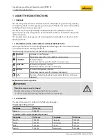
4
Order number 2354920 | Edition 01/2023
Training of Assembly/Commissioning Personnel
Connecting the Airfluid manual system
Connecting the 60 L tank manual system
Grounding the powder coating system
Training the Operating Personnel
Switching on the Manual System
Adjusting the fluidization (Airfluid)
Adjusting fluidization (60 L tank without vibrator table)
Factory setting recipe nos. 1–4
Interrupting the coating process
Double-click recipe (High Dynamic Remote)
Flushing and cleaning the system
Periodic checking of the manual system
Troubleshooting and rectification


