background image

39

Super Finish 23 CR

 CLEANING THE UNIT

CLEANING THE UNIT

A clean state is the best method of ensuring operation with-

out problems. After you have finished work, clean the unit. 

Under no circumstances may coating material rests dry and 

harden in the unit. The cleaning agent used for cleaning (only 

with a flash point above 21 °C) must be suitable for the coat-

ing material used.

Warm water improves the cleaning effect in 

the case of water-dilutable coating materials.

For spray work:

Secure the spray gun, refer to the operating 

manual of the spray gun. Remove and clean 

the tip.

1.  Open the discharge tap.

2.  Set ON/OFF switch to ON.

3.  Turn the pressure control valve back in order to set a mini-

mal pressure.


Only for units with suction system: 

Remove suction sys-

tem from material container, leave return hose in material 

container until hardly any material escapes. Immerse the 

suction system in a suitable cleaning agent.

4.  Close the discharge tap.

5.  Hold the gun or material ball valve/hose whip in an open 

bucket. Pull the trigger on the gun or open the material 

ball valve to pump out the remaining material (if appro-

priate, increase the pressure at the pressure control valve 

slowly in order to obtain a higher material flow).

The container must be earthed in case of 

coating materials which contain solvents.

Caution! Do not pump in a container with 

small opening (bunghole)!

See safety regulations.

6.  Release the trigger on the gun or close the material ball 

cock.

7.  Fill up hopper with suitable cleaning agent.

8.  Open the discharge tap .

9.  Pre-clean the hopper and filter with a brush.

10. Pump suitable cleaning agent in the circuit for several 

minutes.

11.  Close the discharge tap 

12.  Hold the gun or material ball cock/whip hose in an open 

bucket. Pull the trigger on the gun or open the material 

ball cock to pump the cleaning agent out of the hopper. 

Do this by pulling and releasing the trigger on the gun 

several times/opening and closing the material ball cock.

8.1 

CLEANING THE UNIT FROM THE OUTSIDE

First unplug the power plug from the outlet.

Danger of short-circuits caused by water 

ingression! Never spray down the unit with 

high-pressure or high-pressure steam clean-

ers.

Do not put the high-pressure hose into sol-

vents. Use only a wet cloth to wipe down the 

outside of the hose.

Wipe down unit externally with a cloth which has been im-

mersed in a suitable cleaning agent.

8.2 

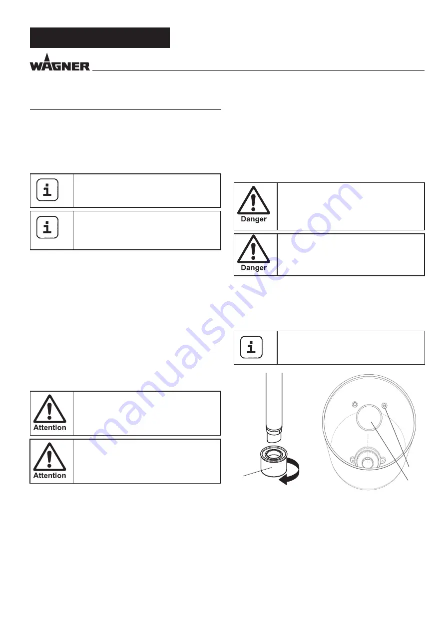
SUCTION FILTER

Clean filters always ensure maximum volume, 

constant spray pressure and problem-free 

functioning of the unit.

Unit with suction system

1.  Unscrew the filter (Item 1) from the suction tube.

2.  Clean or replace the filter. 

Carry out cleaning with a hard brush and a correspond-

ing cleaning agent.

Unit with hopper

1.  Release screws with a screwdriver (Item 2).

2.  Lift and remove filter disk with a screwdriver

3.  Clean or replace the filter disk.


Carry out cleaning with a hard brush and a corresponding 

cleaning agent.

1

2

1

13. Pour new detergent into the container and repeat the 

above procedure 1 or 2 times.

14.  Switch off unit

15.  Open the discharge tap .

Summary of Contents for SUPER FINISH 23 CR

Page 1: ...SUPER FINISH 23CR AIRLESS HIGH PRESSURE SPRAYING UNIT D GB F I 28 RU ...

Page 2: ...e with the operating manual before every start up 1 Faulty units may not be used 2 Secure a Wagner spray gun with the securing lever at the trigger guard 3 Ensure earthing 4 Check the permissible operating pressure of the high pressure hose and spray gun 5 Check all the connecting parts for leaks 3 Instructions for regular cleaning and maintenance of the unit are to be observed strictly Observe th...

Page 3: ..._________________________________ 35 4 1 Gun_______________________________________ 35 4 2 High pressure hose and pressure gauge__________ 36 4 3 Hopper____________________________________ 36 4 4 Suction system______________________________ 36 4 5 Connection to the mains network_______________ 37 4 6 Cleaning preserving agent when starting up of operation initially____________________________ 37 4...

Page 4: ... sur faces etc in the vicinity 1 4 DANGER OF INJURY FROM THE SPRAY JET Attention danger of injury by injection Never point the spray gun at yourself other persons or animals Never use the spray gun without spray jet safety guard The spray jet must not come into contact with any part of the body In working with Airless spray guns the high spray pressures arising can cause very dan gerous injuries I...

Page 5: ...ing due to the flow speed of the coating material These can cause sparks and flames upon discharge The unit must therefore always be earthed via the electrical system The unit must be connected to an appropriately grounded safety outlet An electrostatic charging of spray guns and the high pressure hose is discharged through the high pressure hose For this reason the electric resistance between the...

Page 6: ...acquers and paints or those containing solvents two component coating materials dispersion and latex paints Injection foams one and two component Injection resin one and two component No other materials should be used for spray ing without WAGNER s approval Pay attention to the Airless quality of the coating materials to be processed The unit is able to process coating materials with up to 20 000 ...

Page 7: ...lly and coating material is sucked in During the upwards movement of the diaphragm the coating material is displaced and the outlet valve opens while the inlet valve is closed The coating material flows under high pressure through the high pressure hose to the gun The pressure control valve limits the set pressure in the hy draulic oil circuit and thus also the pressure of the coating material A p...

Page 8: ...re control valve 8 Discharge tap to regulate the flow of the material Open discharge tap points down The material is fed into the hopper mate rial container Closed discharge tap at 90 The material is fed to the gun or to the material ball cock 9 Return tube 10 Hopper 11 Inlet valve button 12 Outlet valve 13 Oil measuring stick 14 Pressure gauge 15 Suction system rigid a and flexible b Accessory Th...

Page 9: ...rement 1 m distance from unit and 1 60 m above floor 12 MPa 120 bar operating pressure reverberant floor 4 STARTUP 4 1 GUN 1 Screw either the whip hose 1 for injection work or the nozzle holder with nozzle 2 for spray work to the gun Before any injection work remove the filter that is premounted in the gun as described below to prevent it from becoming blocked 2 Pull the protective bracket 3 forwa...

Page 10: ...lean Ensure that the red inlet 1 is inserted in the coat ing material inlet 4 2 Screw the union nut 5 on the return pipe 6 onto the connection 7 spanner width 22mm 3 Screw the upper hopper 8 onto the coating material in let 4 1 4 5 6 7 8 9 10 4 4 SUCTION SYSTEM 1 Ensure that the sealing surfaces of the connections are clean Ensure that the red inlet 1 is inserted in the coa ting material inlet 4 2...

Page 11: ... collecting container 4 8 TAKING THE UNIT INTO OPERATION WITH COATING MATERIAL 1 Open the discharge tap 5 2 Pour coating material into the hopper or dip the suction system into the material container 3 Press inlet valve pusher 4 several times to release pos sibly clogged inlet valve 4 Set ON OFF switch 1 to ON the unit will start 5 Turn the pressure regulating knob 2 to the right until the stop is...

Page 12: ...lding The risk of damage rises with the age of the high pressure hose Wagner recommends replacing high pres sure hoses after 6 years Only use WAGNER original high pressure hoses with internal heating in order to ensure functionality safety and durability 7 INTERRUPTION OF WORK If using quick drying or two component coating materials do not fail to rinse unit through with a suitable cleaning agent ...

Page 13: ...n the gun or close the material ball cock 7 Fill up hopper with suitable cleaning agent 8 Open the discharge tap 9 Pre clean the hopper and filter with a brush 10 Pump suitable cleaning agent in the circuit for several minutes 11 Close the discharge tap 12 Hold the gun or material ball cock whip hose in an open bucket Pull the trigger on the gun or open the material ball cock to pump the cleaning ...

Page 14: ... by technicians for safety reasons Please observe all the applicable na tional regulations You can servicing of the unit carried out by the Wagner Service Favourable conditions can be agreed with a service agreement and or maintenance packages Minimum check before every startup 1 Check the high pressure hose gun with rotary joint pow er supply cable with plug for damage 2 Check whether the pressur...

Page 15: ...rn out the inlet valve carefully 6 Clean the valve seat 4 with a cleaning agent and brush ensure that no brush hairs are left behind 7 Clean the seals 5 6 and check for damage Replace if necessary 8 Check all the valve parts for damage In case of visible wear replace the inlet valve Installation 1 Insert the inlet valve 2 into the trigger housing 1 and secure with the clasp 3 Ensure that the black...

Page 16: ...s 4 Check the O ring 7 for damage 5 Check the installation position when mounting the spring support ring 3 clipped onto spring 2 outlet valve seat 5 and seal 6 refer to figure 10 5 TYPICAL WEAR PARTS Inlet valve spare part Order No 2393043 For replacing refer to Section 10 2 failure becomes noticeable through performance loss and or poor or no suction Outlet valve spare part Order No 2393106 For ...

Page 17: ...ucked in Air in the oil circuit Bleed the oil circuit in the unit by turning the pressure control valve completely to the left until overturning and let it run approx 2 3 min Then turn the pressure control valve to the right and set the pressure repeat process several times if necessary Not enough oil Check the oil level Pressure collapses dur ing work this can be seen on the pressure gauge Suctio...

Page 18: ...bject to strict checks under Wagner quality assurance Wagner exclusively issues extended guarantees to commercial or professional users hereafter referred to as customer who have purchased the prod uct in an authorised specialist shop and which relate to the products listed for that customer on the Internet under www wagner group com profi guarantee The buyer s claim for liability for defects from...

Page 19: ...ng accessory parts additional components or spare parts that are not original Wagner parts for products to which modifications or additions have been carried out for products where the serial number has been removed or is illegible for products to which attempts at repairs have been carried out by unauthorised persons for products with slight deviations from the target properties which are negligi...

Reviews: