GRUPPI DI VERNICIATURA AIRLESS TECNI /
SPRAY PAINTING EQUIPMENT
GROUPES DE PULVERISATION /
LACKSPRITZGERÄTE
80
ZZ108
i) Procedere al rimontaggio della
pompa facendo attenzione al corret-
to orientamento delle guarnizioni.
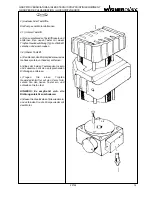
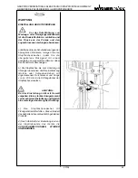
I) Serrare orizzontalmente lo stelo in
morsa, montare le guarnizioni con i
relativi reggispinta, mettere qualche
goccia di “liquido frena filetti” (ad
esempio Loctite 542) sugli ultimi fi-
letti del corpo valvola stelo ed avvi-
tarlo senza bloccarlo.
m) Lubrificare “moderatamente” le
guarnizioni, introdurre lo stelo nel ci-
lindro facendo sporgere da quest’ul-
timo I’estremità del corpo valvola ste-
lo. Avvitare il corpo valvola sino a che
lo scorrimento del cilindro non risulti
difficoltoso.
n) Introdurre le guarnizioni nel corpo
premistoppa, previa “ moderata”
lubrificazione, quindi completare il
montaggio.
NOTA: Mentre si introduce lo ste-
lo, e consigliabile servirsi della
ghiera premistoppa per evitare
I’espulsione delle guarnizioni.
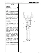
o) Accoppiare la pompa al motore e,
procedere al collaudo del pompante
utilizzando un solvente al fine di ri-
muovere il lubrificante utilizzato per
il montaggio.
NOTA: Smaltire il solvente impie-
gato per il lavaggio secondo le
norme vigenti .
i) Reassemble the pump, making
sure you position the gaskets
correctly.
I) Place the rod in a horizontal
position and clamp it in a vise; put
ths gaskets and their thrust bearings
back into place, applying a few drops
of ‘thread locking liquid’ (such as
Loctits 542) to the end threads of the
rod valve body. Screw the rod valve
body back into place, making sure it
has still room to move (i.e.: it is not
blocked).
m) “Moderately” oil the gaskets, insert
the rod into the cylinder so as to have
the rod valve body jutting out of the
latter. Screw the valve body until the
cylinder slides with difficulty.
n) Insert the gaskets into the gland
body, after you have “moderately”
oiled it, and then finish assembling it.
NOTE: While inserting the rod,
resort to the gasket packing to
prevent the gaskets from being
pushed out.
o) Connect the pump to the motor and
proceed to test the pumping element,
using solvent to remove the oil used
for the assembly.
NOTE: Dispose of the solvent used
for the washing in compliance with
the regulations in force.
i) Remonter la pompe, en orientant
correctement les garnitures.
l) Bloquer horizontalement la tige
dans l’étau, monter les garnitures et
les butées, verser quelques gouttes
de “liquide arrêt-filets” (par exemple,
Loctite 542) sur les derniers filets du
groupe clapet/tige. Serrer la tige sans
la bloquer.
m) Lubrifier “modérément” les
garnitures, introduire la tige dans le
cylindre en faisant sortir de celui-ci
le bout du groupe clapet/tige. Visser
le groupe clapet/tige jusqu’au point
où le cylindre coulisse avec difficulté.
n) Insérer les garnitures dans le
groupe presse-étoupe, après l’avoir
“modérément” lubrifié, puis compléter
l’assemblage.
NOTE: En insérant la tige,
employer la bague presse-étoupe
per éviter l’éjection des garnitures.
lois en vigueur.
o) Coupler la pompe au moteur et
l’essayer avec un solvant pour
enlever le lubrifiant employé pour
l’assemblage.
NOTE: Evacuer le solvant
employé pour le lavage d’après les
lois en vigueur.

