TITANUS
SUPER·SENS
®
Commissioning
TSS_07_A-en-e Data:
02/09
7
– 9
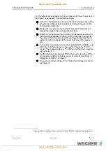
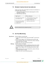
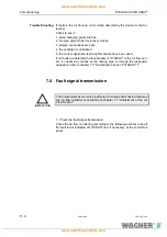
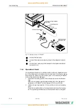
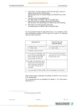
3. Close the 4.2 mm-air sampling points of the test pipe by means of
adhesive tape after the learning phase.
After approximately 75 s the fault display of TITANUS
®
has to start
flashing.
4. Open the 4.2 mm-air sampling points.
The fault display of TITANUS
®
has to extinguish again.
5. Open the 4.6 mm-air sampling points at the testing pipe.
After about 85 s the fault display of TITANUS
®
has to start flashing.
6. Close the 4.6 mm-air sampling points again.
The fault display of TITANUS
®
has to extinguish again.
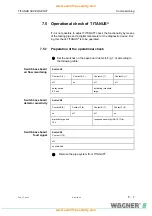
For the operational check the diagnostic device or the connection cable
with the diagnostic interface can be used as an option. The following
steps are to be considered:
Diagnostic device
Connection cable with
diagnostic interface
1. The diagnostic device is connected to a
PC
1F
1 (COM1, COM2)
1. The connection cable is connected to a
PC
2F
1 (COM1, COM2)
2. The diagnostic program is started.
3. The receiving-LED of the diagnostic de-
vice is put over the infrared-diagnostic
LED of TITANUS
®
and is operated
through pressing the ON-button.
3. The connection cable is connected to
the terminals X 2.16 und X 2.17 with its
remaining end (2 wires).
3a. The display of the diagnostic device is
flashing every second as long as the
device is put over the infrared-LED,
which means as long as data are
transmitted.
4. The current data of TITANUS
SUPER · SENS
®
are visualized on the PC-screen.
After a fault has been eliminated the settings of switch S1 are to be reset
to the original state.
The commissioning is to be repeated from chapter 7.1 "Air Flow Sensor
Adjustment" on.
1 PC with serial interface and WIN 95

