TITANUS
SUPER·SENS
®
Pipe
Design
TSS_04_A-en-e
Data: 02/09
4 –
21
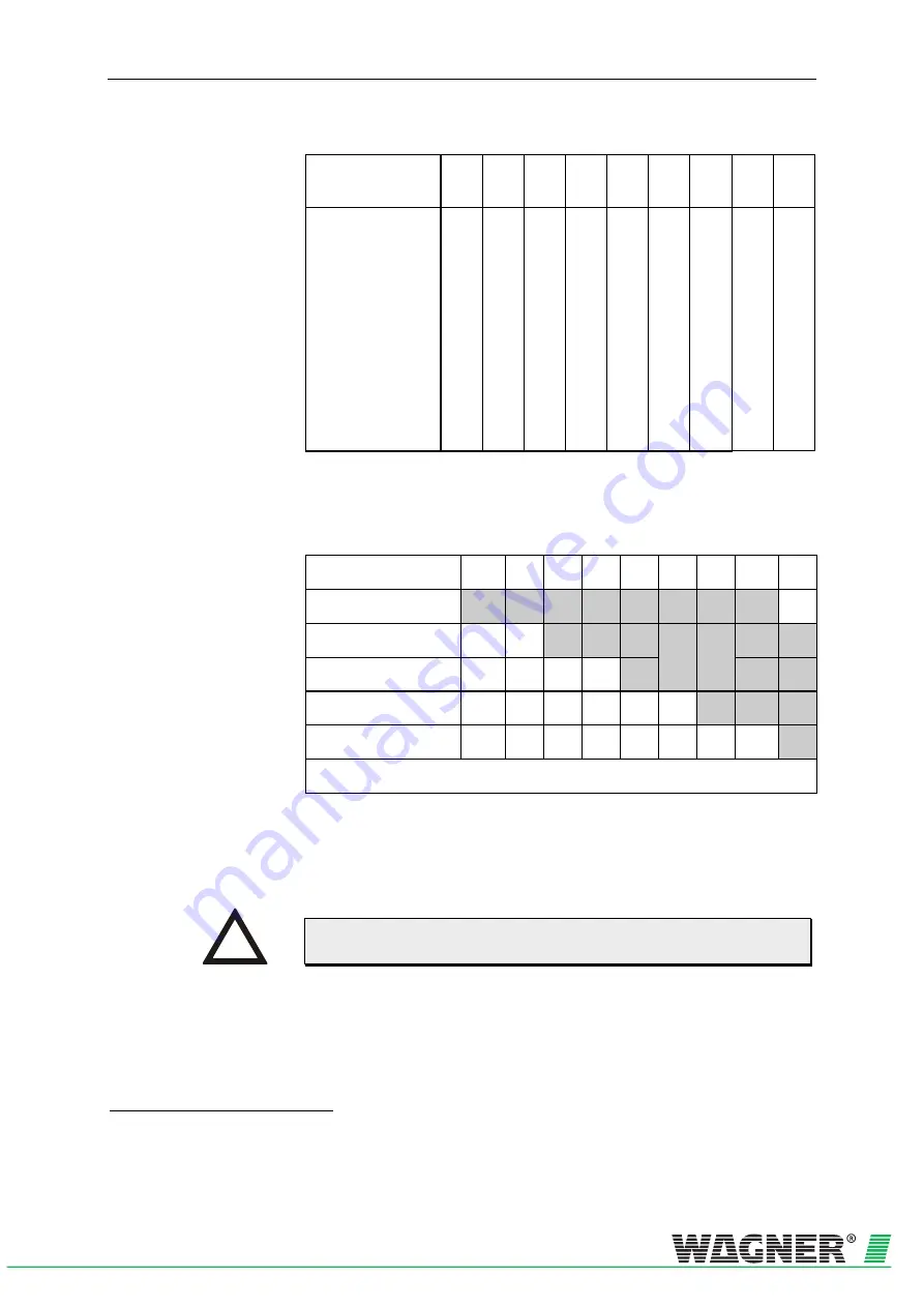
Aspiration apertures
Number of aper-
tures
2 3 4 5 6 7 8 9 10
Sampling aperture
∅
in mm
3F
4
)
A
B
C
D
E
F
G
H
I
J
6,8
6,8
—
—
—
—
—
—
—
—
5,2
5,6
5,6
—
—
—
—
—
—
—
4,4
4,6
5,0
5,2
—
—
—
—
—
—
3,8
4,0
4,2
4,4
4,6
—
—
—
—
—
3,4
3,6
3,6
3,8
4,0
4,0
—
—
—
—
3,2
3,4
3,4
3,6
3,8
4,0
4,2
—
—
—
3,0
3,0
3,2
3,2
3,4
3,6
3,8
4,0
—
—
3,0
3,0
3,2
3,2
3,4
3,6
3,8
3,8
4,0
—
3,0
3,0
3,2
3,2
3,4
3,6
3,8
3,8
4,0
4,0
I-pipe system triggering thresholds
Triggering threshold
Number of apertures
2
3
4
5
6
7
8 9
10
1
blocked aperture
III
III
III
III
II
II
I
I —
4F
5
2
blocked apertures
{
5F
6
{
III
III
III
III
II
II
I
3
blocked apertures
{
{
{
{
III
III
III
III
II
4
blocked apertures
{
{
{
{
{
{
III
III
III
5
blocked apertures
{
{
{
{
{
{
{
{
III
… has/have been detected at setting level x
Example
If blockage of 1 aspiration apertures of a total of 9 aspiration aper-
tures is intended to be detected, the air flow monitoring setting
switch should be set to level I.
Air flow monitoring level I, II or III should be set in any case for project
planning in conformity with EN 54-20.
4
Press cut diameter in aspiration-reducing film sheet
5
— not possible
6
{
not purposeful
INSTRUCTION


