TITANUS
SUPER·SENS
®
Pipe
Design
TSS_04_A-en-e
Data: 02/09
4 –
41
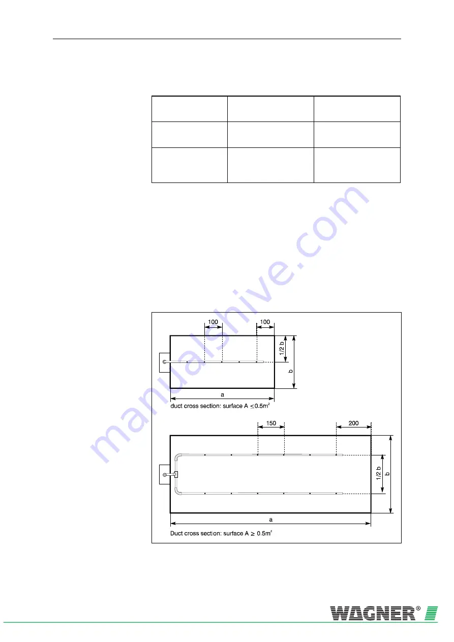
The distances of the aspiration apertures to each other and to the wall of
the duct are represented in the following table.
Bore distance
Duct cross section
≤
0.5 m²
Duct cross section
> 0.5 m²
Distance from aspiration
apertures to wall
100 to 200 mm
200 to 300 mm
Distance of aspiration
apertures to one an-
other
100 mm
150 mm
Sampling
aperture
diameter
The diameter of the sampling aperture results from the number of aspira-
tion apertures. The precise value can be found in Chapter 4.3.2 "Simpli-
fied pipeline project planning”.
The pipe is concluded with an end cap without a bore.
Arrangement
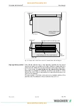
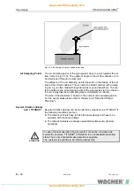
The aspiration apertures should be arranged against the air flow.
During project planning, it is to be taken into account that the air condi-
tioning ducts for mounting the pipe system are often only accessible from
two sides.
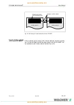
Example
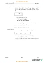
The following illustration depicts two project planning examples of pipe
systems in air conditioning ducts.
Fig. 4.26: Ducts with small and large duct cross-section


