TITANUS
SUPER·SENS
®
Installation
TSS_05_A-en-e Data:
02/09
5
– 5
5.3.1.4
Setting of the Response Sensitivity
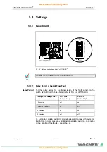
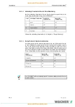
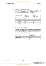
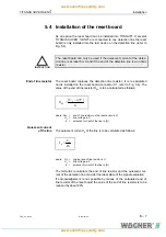
The sensitivity of the detector head is usually set via the switch S2 (G, H)
on the base board (refer to
3H
Fig. 5.2) of TITANUS
®
. The following table
shows the response sensitivity (fire alarm) of TITANUS
®
.
Level
TITANUS
®
Switch S2
Contact G (7)
Switch S2
Contact H (8)
I 0,2%/m
on
on
II
0,1%/m (Standard)
off
on
III 0,05%/m
on
off
IV 0,025
%/m
off
off
5.3.1.5
Fault and Alert Alarm Display
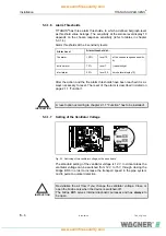
The display for collective faults (air flow and detector head fault) as well
as the display and signal of the alert alarm can be set latched (standard)
or non-latched. A homogenous setting can only be effected via switch S2,
contact J (refer to
4H
Fig. 5.2) of TITANUS
®
.
Fault and Alert Alarm Signal
Switch S2
Contact J (10)
latched (standard)
on
non-latched off

