background image

4

VERSION 02/2019

ORDER NUMBER DOC 2397374
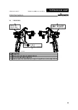
TOPFINISH GM 1030P

ASSEMBLY AND COMMISSIONING 

19

6.1 

Training of Assembly/Commissioning Personnel 

19

6.2 

Storage Conditions 

19

6.3 

Installation Conditions 

20

6.4 

Installation and Connection 

20

6.4.1 

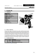
Typical Airspray Spraying System 

20

6.4.2 

Ventilation of the Spray Booth 

20

6.4.3 

Air Supply Lines 

21

6.4.4 

Product Supply Lines 

21

6.5 Grounding 

21

6.6 

Safety Checks 

21

6.7 

Lacquer Preparations 

21

6.8 Commissioning 

22

6.8.1 Procedure 

22

6.8.2 

Verifying a Safe Operational Condition 

22

7 OPERATION 

23

7.1 

Training the Operating Personnel 

23

7.2 Tasks 

23

7.2.1 

Starting to Spray with the Airspray 

23

7.3 

Adjusting the Spray Pattern 

24

7.3.1 

Adjusting Spray Pattern 

25

7.3.2 

Setting the Product Flow Rate 

25

7.4 

Pressure Relief / Work Interruption 

27

7.5 

Cleaning the Nozzle and Eliminating Nozzle Clogging 

28

CLEANING AND MAINTENANCE 

29

8.1 Cleaning 

29

8.1.1 

Safety Instructions 

29

8.1.2 

Cleaning Personnel 

29

8.1.3 

Flushing and Cleaning the Spray Gun 

29

8.2 Maintenance 

30

8.2.1 

Maintenance Personnel 

30

8.2.2 

Safety Instructions 

30

8.2.3 

Safety Checks and Maintenance Intervals 

31

8.2.4 

Replacing the Product Hose or Air Hose 

32

TROUBLESHOOTING AND RECTIFICATION 

33

10 

REPAIR WORK 

34

10.1 

Repair Personnel 

34

10.2 

Repair Notes 

34

10.3 Tools 

35

10.4 

Changing Needle Packings 

36

10.5 

Changing the Air Valve 

37

10.6 

Changing Shaping Air Regulator 

38

10.7 

Changing Shaping Air Regulator 110 

39

10.8 

Tightening Nozzle Nut 

40

10.9 

Replacing Nozzle or Needle 

41

Summary of Contents for TOPFINISH GM 1030P

Page 1: ...B_06965 TOPFINISH GM 1030P Airspray manual gun for flat and round jet nozzles Version 02 2019...

Page 2: ......

Page 3: ...pe Plate 10 4 BASIC SAFETY INSTRUCTIONS 11 4 1 Safety Instructions for the Operator 11 4 1 1 Electrical Devices and Equipment 11 4 1 2 A Safe Work Environment 11 4 1 3 Personnel Qualifications 12 4 2...

Page 4: ...sting the Spray Pattern 24 7 3 1 Adjusting Spray Pattern 25 7 3 2 Setting the Product Flow Rate 25 7 4 Pressure Relief Work Interruption 27 7 5 Cleaning the Nozzle and Eliminating Nozzle Clogging 28 8...

Page 5: ...2 12 DISPOSAL 43 13 ACCESSORIES 44 13 1 Air caps 44 13 2 Nozzles and Needles 45 13 3 Nozzles 45 13 4 Hose Sets 46 13 5 Additional Accessories 47 14 SPARE PARTS 48 14 1 How Can Spare Parts Be Ordered 4...

Page 6: ...SYMBOLS IN THESE INSTRUCTIONS Warning instructions in this manual highlight particular dangers to users and to the device and state measures for avoiding the hazard These warning instructions fall in...

Page 7: ...r pressure tank Personnel qualifications Trained person Is instructed in the tasks assigned to him her the potential risks associated with improper behavior as well as the necessary protective devices...

Page 8: ...trained on the basis of this operating manual 2 3 FOR USE IN POTENTIALLY EXPLOSIVE AREAS The device is suitable for use in potentially explosive areas as defined in Directive 2014 34 EU ATEX see Expl...

Page 9: ...uct temperature This and the permissible ambient temperature can be found in Chapter 5 4 2 Safe Handling of WAGNER Spray Devices Mechanical sparks can form if the device comes into contact with metal...

Page 10: ...6 3 1 max p air max p fluid 8 bar 116 psi II 2G X YB SN YY XXXX GM 1030P Wagner Int AG CH 9450 Altstaetten 2 Designation 1 Maximum air inlet pressure product pressure 2 Spray gun model and manufacture...

Page 11: ...ctive ground wire connection Keep liquids away from electrical devices 4 1 2 A SAFE WORK ENVIRONMENT Hazard due to dangerous fluids or vapors Severe or fatal injuries due to explosion hazard or inhala...

Page 12: ...uctions The device must only be operated maintained and repaired by trained personnel Refer to the operating instructions for information about the required personnel qualifications 4 2 SAFETY INSTRUC...

Page 13: ...12 months for their work safe condition in accordance with DGUV regulation 100 500 Chapter 2 29 and Chapter 2 36 For shut down devices the examination can be suspended until the next start up In the...

Page 14: ...the device The electrical resistance of the product hose measured at both valves must be less than 1 M Suction hoses may not be subjected to pressure 4 2 5 CLEANING AND FLUSHING Danger due to cleanin...

Page 15: ...ervice center or a suitably trained person may carry out repairs and replace parts Use only WAGNER original spare parts and accessories Do not change or modify the device if change is necessary contac...

Page 16: ...ce tobecoated Theclosingofthesprayguntakesplaceinthereverseorder Theproductflow rate is dependent on the diameter of the nozzle I and the setting of the material pressure on the pressure vessel or pro...

Page 17: ...um air inlet pressure bar MPa psi 8 0 8 116 recommended 2 0 2 29 Maximum product pressure bar MPa psi 8 0 8 116 Fluid inlet inch G3 8 Air connection inch G1 4 Weight g oz 486 17 1 pH range of the prod...

Page 18: ...272 343 412 485 HVLP flat 2 206 323 429 540 651 770 HVLP round 3 109 171 230 293 352 416 HVLP flat 4 163 246 329 410 493 579 Conv12 round 5 110 172 232 293 351 418 Conv12 flat 6 173 264 352 437 529 6...

Page 19: ...y regulations for the additionally required system components A skilled person must check to ensure that the device is in a reliable state after it is assembled and commissioned 6 2 STORAGE CONDITIONS...

Page 20: ...appy to assist you in creating a spraying system solution that meets your individual needs You must familiarize yourself with the operating manuals and the safety regulations of all additional system...

Page 21: ...stant to the sprayed products Ensure that the spray gun fittings and product hose between the device and the spray gun are suitable for the pressure generated in the device Ensure that the following i...

Page 22: ...s 5 Make sure that the device and all other conductive parts within the work area are grounded 6 To perform a tightness check on the entire installation the product pressure is slowly increased in inc...

Page 23: ...sioning is carried out in accordance with Chapter 6 8 7 2 1 STARTING TO SPRAY WITH THE AIRSPRAY 1 Start up with product supply set to approx 0 05 to 0 15 MPa 0 5 to 1 5 bar 7 to 22 psi operating press...

Page 24: ...has very coarse droplet distribution Increase the atomizing air pressure B_06980 Material application is very thin in the middle of the spray pattern Reduce the atomizing air pressure B_06981 The spra...

Page 25: ...y oval shaped b If the shaping air regulator 1 is rotated clockwise the spray pattern is narrowed and increasingly round 7 3 2 SETTING THE PRODUCT FLOW RATE The flow rate can be adjusted by screwing t...

Page 26: ......

Page 27: ...aying system include Air cock with pressure relief hole mounted between compressed air source and pneumatic pump Outlet equipment return valve mounted between pump and spray gun Pressure relief proced...

Page 28: ...pray gun and product pressure generator A B B_06971 C E D 12 Nm 8 85 lbft 2 Unscrew air cap nut A 3 Remove air cap B 4 Unscrew nozzle nut C with a size 13 wrench remove air control ring D and Airspray...

Page 29: ...ent grounding and all devices ready to use 2 Relieve the pressure of the product pressure generator and of the spray gun in accordance with Chapter 7 4 3 Close air pressure regulator 4 Dismount air ca...

Page 30: ...rson may carry out repairs and replace parts Use only WAGNER original spare parts and accessories Only repair and replace parts that are listed in the Spare parts chapter and that are assigned to the...

Page 31: ...sbetweenproductpressuregeneratorandapplication device is reduced due to environmental influences even when handled correctly Check hoses pipes and couplings every day and replace if necessary Before e...

Page 32: ...t of the product connection and hold it in place 5 Unscrew the product hose nut using the size B wrench Air hose 4 Place the size D wrench on the air connection and hold it in place 5 Unscrew the air...

Page 33: ...sting screw Poor spray pattern Incorrectly adjusted atomizing air Readjust the atomizing air Unfavorable nozzle size Select a different nozzle 13 Product pressure too high too low Adapt product pressu...

Page 34: ...y out repairs and replace parts Use only WAGNER original spare parts and accessories Only repair and replace parts that are listed in the Spare parts chapter and that are assigned to the unit Before a...

Page 35: ...Designation Smaller tanks 9992831 1 pc 50 ml Loctite 542 9992590 1 pc 50 ml Loctite 222 9992698 1 pc 200 g Vaseline white PHHV II 9992616 1 pc 1 kg can Molykote DX grease 50 g tube order no 2355419 V0...

Page 36: ...edle from the rear As necessary slightly loosen the clamping sleeve C of the needle packing B 5 Loosen the clamping sleeve C of the needle packing B with a size 7 wrench 6 Unscrew needle packing B and...

Page 37: ...gun in accordance with Chapter 7 4 3 Unscrew locking cap A with a size 16 wrench 4 Carefullyremovepressurespring B andunscrewairvalve C withasize10Allenwrench 5 Replace air valve C coat with Loctite...

Page 38: ...n in accordance with Chapter 7 4 3 Carefully insert rod seal A in the foreseen notch on the gun Ensure that the installation position is correct see sectional view Ideally place the rod seal A on a fl...

Page 39: ...ing screw it back in and completely unscrew the threaded sleeve B 3 If necessary pull out the rod seal A with a small screwdriver and then replace it with a new one Assembly 1 Carefully insert rod sea...

Page 40: ...the product pressure generator and of the spray gun in accordance with Chapter 7 4 3 Remove air cap nut A and air cap B 4 Check nozzle nut C for correct seating and if necessary tighten with a size 13...

Page 41: ...le packing 5 Remove air cap nut A and air cap B 6 Unscrew nozzle nut C with a size 13 wrench remove air control ring D and nozzle E 7 Treat parts with cleaning agent until all remaining paint has been...

Page 42: ...isual inspection Trigger and flush the spray gun multiple times Check the following Is the product connection sealed when the gun is closed Is the product valve sealed Is there no product discharge at...

Page 43: ...he devices must be scrapped please differentiate the disposal of the waste materials The following materials have been used Stainless steel Aluminum Brass Plastics Theconsumableproducts lacquers adhes...

Page 44: ...ONV 10 2401172 Air cap 0 3 1 8 mm CONV 12 Base lacquer colored lacquer clear lacquer separating agent B_07078 2401173 Air cap 2 0 2 5 mm CONV 12 2401174 Air cap 0 3 1 8 mm CONV 14 Base lacquer colored...

Page 45: ...GM 1030P nozzle needle set 2 0 mm 2400793 GM 1030P nozzle needle set 2 2 mm 2400794 GM 1030P nozzle needle set 2 5 mm 2400795 GM 1030P nozzle needle set 3 0 mm 2400796 GM 1030P nozzle needle set 3 5...

Page 46: ...07146 1 Designation 1 Hose set complete 2 Air hose 3 Product hose 4 Protective hose For configurations see following table Order no Designation 1 2405455 LP hose set Flex DN6 7 5 m 1 2405456 LP hose s...

Page 47: ...010102000 Hose connector 8 mm brass V0010103000 Union nut G 1 4 nickel plated brass V7013150000 Hose clamp 13 15 2403453 Shaping air regulation 110 set B_07084 2401072 Product tube with filter complet...

Page 48: ...lists Wearing parts Wearing parts are not included in the warranty terms Included in service set Note These parts are not covered by warranty terms Not part of standard equipment however available as...

Page 49: ...r 13 1 3 1 2400782 Nozzle nut 4 1 2400779 Air control ring 5 1 Nozzle needle set see Chapter 13 2 6 1 2400776 Nozzle holder set 7 1 2400775 Product connection set 8 1 2400781 Air connection 9 1 240077...

Page 50: ...ailable as a special accessory 15 EU DECLARATION OF CONFORMITY Herewith we declare that the supplied version of Topfinish GM 1030P complies with the following guidelines 2006 42 EC 2014 34 EU Applied...

Page 51: ......

Page 52: ...52 CERTI F I E D ts liquid wagner group com www wagner group com Order no 2397374 Edition 02 2019 Document No 11219765 Version A...

Reviews: