background image

Irrtümer und Änderungen vorbehalten. 
Not responsible for errors and changes. 
Sous réserves d’erreurs et de modifications. 
Fouten en wijzigingen voorbehouden.

J. WAGNER GMBH

Otto-Lilienthal-Str. 18
88677 Markdorf
T +49  0180 -  55 92 46 37
F +49 075 44 -5 05 11 69

WAGNER SPRAYTECH (UK) LTD

Opus Park
Moorfield Road
Guildford Surrey GU1 1SZ
T +44 (0) 1483 - 454666
F + 44 (0) 1483 - 454548

WAGNER FRANCE S.A.R.L.

12 Avenue des Tropiques
Z.A. de Courtaboeuf
91978 Les Ulis Cedex
T +33  0825 011 111
F +33 (0) 1 69 81 72 57


MAKIMPORT 

HERRAMIENTAS, S.L.

C/ Méjico nº 6   
Pol. El Descubrimiento
28806 Alcalá de Henares (Madrid) 
T 902 199 021   /   91 879 72 00
F 91 883 19 59

ORKLA HOUSE CARE DANMARK A/S


Stationsvej 13
3550 Slangerup
Danmark
T +45 47 33 74 00  
F +45 47 33 74 01 

WAGNER SPRAYTECH 

AUSTRALIA PTY. LTD.,

14 -16 Kevlar Close
Braeside, VIC 3195
T +61  3 95 87 - 20 00
F +61  3  95 80 - 91 20

J. WAGNER AG

Industriestraße 22
9450 Altstätten
T +41  71 - 7 57 22 11 
F +41  71 - 7 57 23 23 

HONDIMPEX KFT.

Kossuth L. u. 48-50
8060 Mór
T +36 (-22) - 407 321  
F +36 (- 22) - 407 852

E-CORECO SK S.R.O.

Kráľovská ulica 8/7133
927 01 Šaľa
T +42 1948882850 
F +42 1313700077


PUT WAGNER SERVICE

ul. E. Imieli 27
41-605 Swietochlowice
T +48/32/346 37 00  
F +48/32/346 37 13


D

F

DK

S

CH

AUS

H

PL

GB

E

SK

P

ORKLA HOUSE CARE AB

Box 133
564 23 Bankeryd
Sweden
T +46(0)36 37 63 00

ROMIB S.R.L.

str. Poligonului nr. 5 - 7
100070 Ploiesti ,judet Prahova
T +40-344801240 
F +40-344801239

ROM

ORKLA HOUSE CARE NORGE AS

Nedre Skøyen vei 26,
PO Box 423, Skøyen
0213 Oslo
T +47 22 54 40 19 

NOR

E-CORECO S.R.O.

Na Roudné 102
301 00 Plzeň
T +42  734 792 823  
F +42  227 077 364


CZ

Part. No. 2361944  F 
11/2017_RS 
© Copyright by J.Wagner GmbH

FHC SRL

Via Stazione 94,
26013 Crema (CR)
T  0373 204839  
F  0373 204845

I

Summary of Contents for W 990 FLEXIO

Page 1: ...wagner group com D GB NL F UNIVERSAL SPRAYER W 990 FLEXIO ORIGINAL BETRIEBSANLEITUNG ...

Page 2: ...agner group com service Contents 1 Explanation of symbols used 31 2 General Safety Instructions 31 3 Safety instructions for colour application devices 34 4 Scope of delivery 35 5 Field of application 36 6 Coating Materials Suitable for Use 36 7 Coating Materials Not Suitable for Use 36 8 Preparation of the workplace 36 9 Preparation of the Coating Material 37 10 Start up 37 11 Use the Standard sp...

Page 3: ...suited for use with the relevant device 2 General Safety Instructions WARNING Read all safety notifications and instructions Failure to comply with the safety notifications and instructions provided may result in electric shock fire and or serious injury The term power tool used below covers both mains operated powertools withmainslead andaccumulator operatedpowertools without mains lead 1 Safety ...

Page 4: ...ng and work sensibly with a power tool Do not use the tool if you are tired or under the influence of drugs alcohol or medication Just a moment of inattentiveness while using the tool can lead to serious injuries b Wear personal safety equipment and always wear safety goggles Wearing personal protective equipment such as dust mask non slip safety shoes safety helm or ear protection depending on th...

Page 5: ...d Store unused power tools so that they are inaccessible to children Do not let persons use the tool who are not familiar with it or who have not read these instructions Power tools are dangerous when they are used by inexperienced persons e Take proper care of your tools Check whether the moving parts function trouble free and do not jam whether parts are broken or damaged so that the tool functi...

Page 6: ...ns to spray flammable substances The spray guns are not to be cleaned with flammable solvents Caution against dangers that can arise from the sprayed substance and observe the text and information on the containers or the specifications given by the substance manufacturer Do not spray any liquid of unknown hazard potential The device may not be used in workplaces covered by the explosion protectio...

Page 7: ...1 1 Basic device W 990 2 On off switch 3 Height adjustable attachment for paint bucket 4 Suction hose a and filter b 5 Plug for basic device 6 Turbine unit a with air flow limiter b and air filter compartment c 7 Direct Feed spray attachment a with spray jet setting b material flow limiter c and trigger d 8 Material hose a with electric cable b and plug c 9 Strap holder 10 Cleaning brush 11 Stirri...

Page 8: ...ention Never suck solvent based materials directly via the suction system Pumps and hoses are not solvent resistant and could be damaged 7 Coating Materials Not Suitable for Use Materials that contain highly abrasive components facade paint caustic solutions and acidic coating substances Flammable materials The following materials can only be processed with optional accessories Fine plaster maximu...

Page 9: ... and the paint you are using is very thick and gel like dilute it by 10 Dilution can be necessary if the atomisation is coarse or if the flow rate is too low even at the maximum setting Detailed information about the various materials and the maximum permitted dilution can be found on the manufacturers technical data sheets e g available on the Internet Our online database Wagner Spray Guide has t...

Page 10: ...ectly out of the paint bucket If you want to use the Standard spray attachment please continue reading chapter 11 Hold the height adjustable attachment for paint bucket fig 5 5 at the side and pull upwards Position the paint bucket on the ledge fig 6 6 so that the bucket handle is between both fixtures Important The bucket handle must bebetweenbothfixtures Otherwise the bucket could be tipped by t...

Page 11: ...from the gun intermittently and create stains on the wall Tip If the paint bucket is at an angle the contents will be able to be suctioned off entirely Therefore place a small object underneath the paint bucket Plug in the power cable Switch the device on position I at the main switch fig 9 7 Aim the spray gun at a piece of cardboard and depress the trigger until the air has been pumped out of the...

Page 12: ...rom the material hose Connect the Standard spray attachment fig 10 3 to the turbine unit 2 Insert the turbine unit power plug into the socket i Always plug the turbine unit into a separate socket if you are working with the Standard attachment If the turbine unit is connected to the material hose the pump will run unnecessarily which leads to increase wear and tear and energy consumption i Further...

Page 13: ...ient working The spray gun can also be conveniently hooked into place when taking a break from your work Attach the strap holder to the strap or hose Fig 11 Hook the electric cable Fig 12 1 on the material hose into the strap holder If necessary hook the spray gun into the strap holder with the attachment fig 13 2 햿 2 햽 1 햾 ...

Page 14: ...t of Air i Depending on the viscosity of the material to be sprayed and the finish of the object to be coated it may be advisable to vary the amount of air Very low viscosity materials such as watery glazes do not have to be atomised with the maximum amount of air In this case it is advisable to reduce the amount of air and thus minimize the spray vapour This also applies for the use of the Detail...

Page 15: ...ing fig 16 1 Fig 17 A vertical flat jet Æ for horizontal surfaces Fig 17 B horizontal flat jet Æ for vertical surfaces Tightentheunionnut Fig 16 2 fully so that no paint is able to penetrate the device Check regularly whether the union nut has worked loose during operation 16 Setting the width of the spray jet Use the red adjustment lever fig 18 1 to also switch between a wide and a narrow spray j...

Page 16: ...of the area to be sprayed Start the spray movement first of all and then press the trigger Avoid interruptions within the area to be sprayed The spray movement should come from the arm not just from the wrist This ensures that a uniform distance is maintained between the spray gun and the spray surface during the spray operation Select a distance of 10 30 cm depending on the desired spray jet widt...

Page 17: ...em Leave the suction hose in the paint Wet paint surface in paint container with a little water to prevent a skin from forming 19 Transportation fig 21 Important The bucket handle must be between both fixtures Otherwise the bucket could be tipped by the weight of the W 990 when being transported and leak paint Attention Do not pour any liquids over the basic unit Oncethedeviceisattachedtothepaintb...

Page 18: ...rom the turbine unit Do not put the turbine unit anywhere near liquids Never dip the turbine unit into liquids Clean the housing only with a moistened cloth Important The material flow limiter must be set to 12 in order for the stop to be able to move out Pull the trigger backwards fig 24 1 and move out the stop 2 Hook the spray attachment plus fixture fig 25 3 into the paint container so that the...

Page 19: ... Renew the water as required After cleaning pump all the water out of the device and hose With pumps filled with water at temperatures below 0 C there is a risk of frost damage Turn the machine off position 0 and remove the plug Push the stop upwards until you hear it click into place Disconnect the material hose fig 26 1 from thesprayattachmentandremovethecover 2 Pull out the red catch fig 27 3 a...

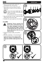
Page 20: ...screen nozzle seal and nozzle with a brush and water Assemble the parts again see Assembly Assembly Attention Never operate the device if the nozzle seal fig 30 6 is either damaged or missing If the nozzle seal is either missing or damaged liquids can enter the device and increase the risk of an electric shock Check the nozzle seal fig 30 6 in the nozzle Place the nozzle fig 31 5 on to the gun bod...

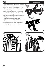
Page 21: ...o horns grip the air cap and the red adjustment lever 8 rests on the pin 9 Click the setting ring into place on the union nut Lubricate the seal fig 35 4 on the pressure reducer and the O ring on the valve 3 Insert valve fig 35 3 into the pressure reducer 2 Insert the pressure reducer fig 35 2 into the spray attachment and secure with the red catch 1 Place the cover fig 36 5 on to the spray attach...

Page 22: ...height adjustable attachment for paint bucket at the side and pull upwards Take the bucket away from the device Push the paint container attachment down Roll up the material hose and power cable tidily making sure they don t kink Pull the yellow handle fig 38 4 out of the device Hook the unrolled material hose fig 39 3 on to the paint container attachment and secure to the device with the handle 4...

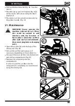
Page 23: ...be sucked in and interfere with the function of the machine Check the air filter after each use for contaminants Disconnect plug before changing parts Open the air filter lid with the help of the stirring rod Fig 42 Pull out the air filter and replace it if necessary depending on how soiled it is First push the new air filter into the bottom part of the compartment Fig 43 Next push it completely i...

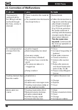
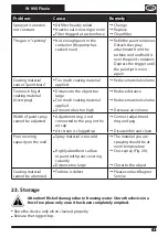
Page 24: ...g material emerges from the nozzle Nozzle clogged Material quantity too small Container empty Suction hose is blocked The suction hose is not in the paint The pressure reducer is clogged up Pump is defect Clean Increase the quantity of material New paint container Clean suction hose Immerse the suction hose Reduce the pressure and clean the pressure reducer fig 26 28 Please contact Wagner Service ...

Page 25: ...Too much coating material applied Amount of air too high Reduce distance Reduce material volume Decrease air volume Width of paint spray cannot be adjusted Adjustment ring is not connected to the peg on the air cap Air screen is clogged up Connect adjustment ring and peg Disassemble and clean Poor covering capacity on the wall Spray material is too cold Highly absorbent surface or paint with poor ...

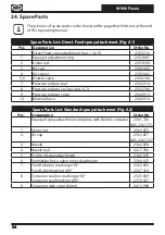
Page 26: ...l 2350 214 8 Pressure reducer cp incl pos 6 7 2353 700 9 Pressure reducer cover 2362 913 10 Material hose 2362 914 Spare Parts List Standard spray attachment Fig A2 Pos Designation Order No Standard spray attachment complete with 800 ml container 2361 730 AUS 2361 731 1 Union nut 2362 873 2 Air cap 2362 877 AUS 2361 747 3 Nozzle 2362 878 4 Nozzle seal 0417 706 5 O ring of spray attachment 2362 875...

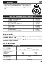
Page 27: ... pos 5 2353 701 5 Suction filter 2356 621 6 Strap holder 2362 916 7 Stirring rod 2304 419 8 Cleaning brush 2362 917 Lubricating grease no fig 2315 539 25 Accessories TheCLICK PAINTSYSTEMwithadditionalsprayattachmentsandaccessoriesoffers the right tool for each work FurtherinformationabouttheWAGNERrangeofproductsforrenovatingisavailable under www wagner group com 26 Technical Data Technical Data Ma...

Page 28: ...ken into consideration here for example periods when the electric tool is switched off and when it is switched on but running without any load Environmental protection The device and all accessories and packaging have to be recycled in an environmentally friendly manner Do not dispose of the appliance with household waste Support environmental protection by taking the appliance to a local collecti...

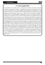
Page 29: ...ns Wearing parts are also excluded from the guarantee The guarantee excludes commercial use We expressly reserve the right to fulfil the guarantee The guarantee expires if the tool is opened up by persons other than WAGNER service personnel Transport damage maintenance work and loss and damage due to faulty maintenance work are not covered by the guarantee Under any guarantee claim there must be p...

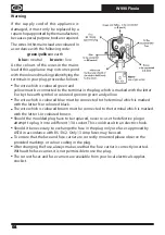
Page 30: ...ed blue must be connected to the terminal which is marked with the letter N or coloured black The wire which is coloured brown must be connected to the terminal which is marked with the letter L or coloured brown Should the moulded plug have to be replaced never re use the defective plug or attempt to plug it into a different 13 A socket This could result in an electric shock Should it be necessar...

Page 31: ...claration of conformity is enclosed with the product If required it can be re ordered using order number 2362410 CE Déclaration de conformité Nous déclarons sous notre responsabilité que ce produit est en conformité avec les réglementations suivantes 2014 35 UE type 0449 2006 42 CE type 0442B 2014 30 UE 2011 65 UE 2012 19 UE Conforme aux normes et documents normalisés EN 60335 1 EN 60335 2 41 pour...

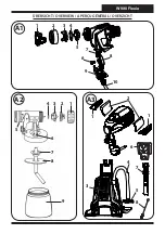
Page 32: ...W 990 Flexio 1 2 7 8 3 4 5 6 9 A2 ÜBERSICHT OVERVIEW APERÇU GÉNÉRAL OVERZICHT A1 1 2 3 4 5 7 6 8 9 10 A3 1 1 2 3 4 5 6 7 8 ...

Page 33: ... of this fold out page The related spare part lists can be found in chapter 24 F Les illustrations des pièces de rechange se trouvent au dos de cette page dépliante Vous trouverez les listes de pièces de rechange correspondantes au chapitre 24 NL Op de achterkant van deze uitklappagina bevinden zich de afbeeldingen van de reserveonderdelen De bijbehorende reserveonderdelenlijsten vindt u in hoofds...

Page 34: ...YTECH AUSTRALIA PTY LTD 14 16 Kevlar Close Braeside VIC 3195 T 61 395 87 20 00 F 61 3 95 80 91 20 J WAGNER AG Industriestraße 22 9450 Altstätten T 41 71 7 57 22 11 F 41 71 7 57 23 23 HONDIMPEX KFT Kossuth L u 48 50 8060 Mór T 36 22 407 321 F 36 22 407 852 E CORECO SK S R O Kráľovská ulica 8 7133 927 01 Šaľa T 42 1948882850 F 42 1313700077 PUT WAGNER SERVICE ul E Imieli 27 41 605 Swietochlowice T 4...

Reviews: