


GB
16
Measuring the Viscosity
Dip the viscosity test cup
(Illus.
)
completely into the spray material. Hold the test cup
up and measure the time (in seconds) until the liquid empties out. Compare the
measured "runout time" with the handling table for viscosity.
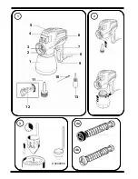
Valve data (handling table page 15)
The nozzle can be removed using the nozzle spanner. The valve is behind the nozzle
and comprises:
1. Atomizer head
2. Spring
3. Valve taper
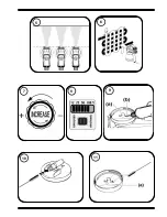
Standard
●
Valve with black atomizer /(stronger spring) - lacquer valve (Illus. 4 a)
Suitable for substances containing solvents and water-diluted paints. The use of this
valve optimises spraying results at reduced delivery rate - electronic settings 50 %,
25 % oder 12 %.
For details refer to handling table page 15.
●
Enclosed valve with white atomizer (weaker spring, softer valve cone) -
plastic-emulsion and latex-paint valve. (Illus. 4 b)
Suitable for water-thinned paints - valve cone more resistant to wear. Use with
maximum delivery rate - electronic setting 100 %.
For details refer to handling table page 15.
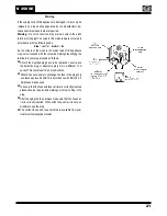
Start-up
1.
Cover areas that are
not
to be sprayed. When woriking keep in mind that wind, for
example, may transport paint mist over great distances and cause damage.
2. Before connecting to the mains supply, please be sure that the supply voltage is
identical with the value given on the rating plate (on the side of the spray gun).
3. Dilute the spray material according the handling table (page 15).
4. Place the container on a sheet of paper and fill it with the prepared spray material.
Attention! Do not operate the spray gun without spray material in the
container; this can lead to increased wear of the pump!
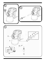
5. Position the spray gun on the container and turn the container to the right until the
container fits tightly
(Illus.
, arrow)
.
6. Activate the switch to start up the spray gun. First the spray gun sucks in spray
material, then after a few seconds the material emerges from the nozzle. To
accelerate the intake, turn the fine adjustment button to maximum.
7. By turning the fine adjustment button you can vary the spray amount
(Illus.
, arrow)
.
Note:
Regulating with the fine adjustment button influences the spray pattern
depending on the spray material and the degree of dilution.
W 450 SE


